RobotChicken’s Mjolnir Mk VI Forearm Armor Detail Parts

Status
Not open for further replies.

RobotChicken

Well-Known Member
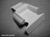
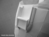
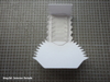
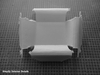
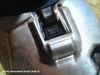
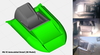
The Mjolnir Mk VI forearm Pepakura armor model lacks a prominent feature at the antecubital space (elbow pit). This feature is completely absent in the normal detail models, and although represented in the High Detail (HD) models, it’s very inaccurate when compared against reference photos:

Intro1.jpg


Intro2.jpg


I chose to create this detail such that the armor pieces more-closely resemble their appearance in photos. Since I’m better with computers than I am at sculpting, and producing a Pepakura file of the detail would enable it to be scaled more easily, the obvious option was design a model for pepping (or 3D-printing for those of you with access to such a magical device). TurboCAD Mac Pro was used to create a 3D model from many wonderful reference photos provided by SirPalesAlot (thank you!).

Intro3.jpg


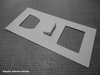
Four versions of the detail were created with incremental degrees of complexity for compatibility with the existing Mk VI forearm models:

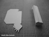
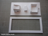
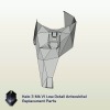
ND (Normal Detail) Mk VI Forearm by ROBOGENESIS
Height = 381
Width = 193
Depth = 180
Scale = 86.0
ND Mk VI Antecubital Detail
screenshot-2316.png

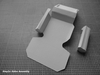
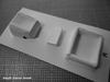
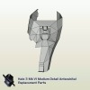
MD (Medium Detail) Mk VI Forearms by flying_squirl
Height = 290
Width = 342 (model includes both forearms)
Depth = 134
Scale = 2.272698
MD Mk VI Antecubital Detail
screenshot-2346.png

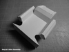
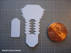
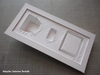
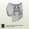
HD (High Detail) Mk VI Forearm by nugget
Height = 330
Width = 177
Depth = 149
Scale = 465.522422
HD Mk VI Antecubital Detail
screenshot-2370.png

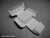
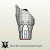
UD (Ultra-High Detail) Mk VI Forearm by SirPalesAlot and RobotChicken
Height = 304
Width = 169
Depth = 135
Scale = 1.0
(Antecubital detail is integrated into the forearm model.)
screenshot-2398.png

3D (3D Printer) Mk VI Forearm by SirPalesAlot and RobotChicken
Height = 304
Width = 159
Depth = 135
Scale = 1.0
(Antecubital area is flat for attaching a 3D-printed detail part.)


Scaling The Model

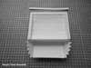
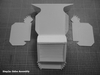
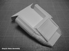
The detail parts are drawn at the same scale as their associated forearms, so simply enter the same Scale value for the antecubital detail model in Pepakura that was used for the forearm model and the parts will print at the correct size. Each of the detail models includes the forearm's perimeter polygons for interfacing with the detail. To avoid having to modify the forearm unfold, these modified perimeter polygons also include the full forearm part they're associated with. This means you can simply swap out forearm parts with the detail parts without needing to get your hands dirty with any changes to the unfolding (unless you want to).

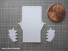
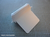
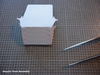
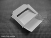
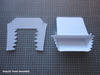
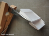
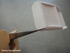
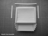
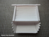
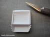
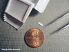
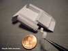
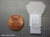
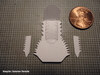
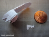
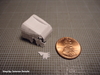
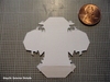
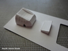
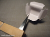
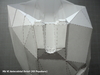
After resizing the detail model to match the scale of your forearm, the page layout will probably need adjusting. The detail models are all drawn for the right forearm, so you will need to Mirror the model in Pepakura (invert it) to print parts for the left forearm. Each file is set up with Edge IDs turned off (the reason why should become obvious if you turn them on), and due to the parts size I’ve set the Lineweight print setting to 1 so they print clearer (hairlines allow for more precise folding and cutting). You’ll see in the photos just how small the pieces were for my child-sized build and I was able to successfully assemble them (tweezers and magnifier lamp were indispensable), so if anything it should be a bit easier with larger, adult-sized, parts.
 

Attachments

  • Intro1.jpg
    Intro1.jpg
    383 KB · Views: 333
  • screenshot-2398.png
    screenshot-2398.png
    6 KB · Views: 294
  • screenshot-2370.png
    screenshot-2370.png
    6.6 KB · Views: 284
  • screenshot-2346.png
    screenshot-2346.png
    5.2 KB · Views: 306
  • screenshot-2316.png
    screenshot-2316.png
    4.8 KB · Views: 290
  • Intro3.jpg
    Intro3.jpg
    306.4 KB · Views: 288
  • Intro2.jpg
    Intro2.jpg
    359.7 KB · Views: 296
Last edited by a moderator:
Step 1: Front Assembly

The first area that should be assembled is the front because it contains flaps which are not accessible for gluing after surrounding areas are built. (You'll probably know how I came about that conclusion...) This starts out with the bottom and two side pieces:

Step1a.jpg


Glue the bottom flaps first, then fold up the back to glue the back flaps:
Step1b.jpg


Next fold down the top and glue its flaps:
Step1c.jpg


After the lower front "pocket" is assembled add the top part:
Step1d.jpg


This should be attached at the front first for aligning the small forward edges:
Step1e.jpg


Again, I use a tweezers for clamping small corners to ensure nothing shifts while the glue sets:
Step1f.jpg


Then attach the back edge and interior flaps for the top concave curved area, finishing with the back side corners:
Step1g.jpg


To add the raised edge detail seen in game screenshots, I cut three strips of cardstock at the same width as the top "frame":
Step1h.jpg


The sides get glued on first:
Step1i.jpg


Then the back strip is added, making sure it conforms into the corners of the side strips:
Step1j.jpg


Lastly it's trimmed even with the outside edges:
Step1k.jpg
 

Attachments

  • Step1a.jpg
    Step1a.jpg
    524 KB · Views: 277
  • Step1c.jpg
    Step1c.jpg
    458.4 KB · Views: 278
  • Step1b.jpg
    Step1b.jpg
    516.1 KB · Views: 275
  • Step1e.jpg
    Step1e.jpg
    320 KB · Views: 292
  • Step1d.jpg
    Step1d.jpg
    479 KB · Views: 283
  • Step1f.jpg
    Step1f.jpg
    401.8 KB · Views: 279
  • Step1g.jpg
    Step1g.jpg
    335.7 KB · Views: 275
  • Step1i.jpg
    Step1i.jpg
    298.1 KB · Views: 296
  • Step1h.jpg
    Step1h.jpg
    309.6 KB · Views: 305
  • Step1j.jpg
    Step1j.jpg
    422.2 KB · Views: 278
  • Step1k.jpg
    Step1k.jpg
    462.8 KB · Views: 269
Step 2: Sides Assembly

The next area that should be assembled are the sides, which can be a bit of a challenge due to their many small parts towards the front. Start by attaching the completed front assembly onto the front of the main body part:

Step2a.jpg


Assemble the two side parts before attaching them onto the main body part:

Step2b.jpg


Step2c.jpg


Step2d.jpg


For easier finishing of the interior detail parts after hardening I opted to build them separately as in the HD file, but with the UD parts rather than the HD parts. That's why you see the interior area with a full bottom face instead of holes for attaching the interior detail parts. This meant combining some of the HD parts with some of the UD parts and customizing their unfolds so they worked together. Unfortunately I messed up and failed to put a flap on an edge where a UD part connects to an HD part. No problem - it just meant I needed to add some scrap cardstock to the inside for holding the corner together on each side:

Step2e.jpg


Step2f.jpg


Next comes a lot of small parts for building the front "torpedo" shapes. Starting from the back, glue each part on the vertical edges only:

Step2g.jpg


Step2h.jpg


Once all the vertical edges are glued, close up the horizontal top seam to finish it off:

Step2i.jpg


Attach the adjoining forearm faces around the perimeter before adding the antecubital detail to the forearm. Otherwise you will have it extremely difficult reaching inside to glue the flaps. (Again you can probably guess how I came about that conclusion and why I don't have a photo of the detail area with surrounding parts attached before adding to the forearm.) But with difficulty, I managed to get them added anyway and they look like this:

Step2j.jpg


You might notice in that last photo that the front area is smoother than the previous photo. That's because I decided to revise their unfold when the parts didn't fit the forearm opening on the first time around. The File Archive downloads are updated with this revised unfold which makes it easier to align the edges and also yields a quicker build due to fewer parts.
 

Attachments

  • Step2a.jpg
    Step2a.jpg
    288.2 KB · Views: 282
  • Step2b.jpg
    Step2b.jpg
    293.3 KB · Views: 308
  • Step2c.jpg
    Step2c.jpg
    322.8 KB · Views: 273
  • Step2d.jpg
    Step2d.jpg
    273.2 KB · Views: 277
  • Step2e.jpg
    Step2e.jpg
    312.9 KB · Views: 296
  • Step2f.jpg
    Step2f.jpg
    274.8 KB · Views: 287
  • Step2g.jpg
    Step2g.jpg
    542.3 KB · Views: 303
  • Step2h.jpg
    Step2h.jpg
    433.5 KB · Views: 287
  • Step2i.jpg
    Step2i.jpg
    316.2 KB · Views: 281
  • Step2j.jpg
    Step2j.jpg
    232.8 KB · Views: 289
Step 3: Interior Details

As mentioned in step 2, I opted to build the interior details separate from the main assembly for easier access during later hardening and finishing. The center "box" is pretty straightforward:

Step3a.jpg


Next I built the rounded block, starting with its concave top area:

Step3b.jpg


Step3c.jpg


Step3d.jpg


Next the sides are put on, starting from the back:

Step3e.jpg


Step3f.jpg


Step3g.jpg


Lastly it too gets attached to a parts holder for handling during hardening and finishing:

Step3h.jpg


The final interior detail part is a square ring with rounded tops. This was quite a challenge at child scale, and the Silhouette Cameo I use for cutting out parts had fun mangling up the minuscule flaps. (I need to get a new blade for the machine.)

Step3i.jpg


Step3j.jpg


Again I used clamped tweezers for holding flaps while the glue sets to ensure tight square corners:

Step3k.jpg


I did my best at getting the corner parts installed, but because this part is so tiny for me it didn't turn out as well as a larger version would. No concern, though, as I can easily "fix it in post" with Bondo.

Step3l.jpg


I made a frame from mat board and attached it on the backside to help support the parts holder while during hardening and finishing:

Step3m.jpg


Step3n.jpg
 

Attachments

  • Step3a.jpg
    Step3a.jpg
    320.3 KB · Views: 289
  • Step3b.jpg
    Step3b.jpg
    536.6 KB · Views: 276
  • Step3c.jpg
    Step3c.jpg
    496.8 KB · Views: 307
  • Step3d.jpg
    Step3d.jpg
    470.6 KB · Views: 271
  • Step3e.jpg
    Step3e.jpg
    525.4 KB · Views: 251
  • Step3f.jpg
    Step3f.jpg
    500.1 KB · Views: 259
  • Step3g.jpg
    Step3g.jpg
    482.8 KB · Views: 232
  • Step3i.jpg
    Step3i.jpg
    540 KB · Views: 246
  • Step3h.jpg
    Step3h.jpg
    380.1 KB · Views: 253
  • Step3j.jpg
    Step3j.jpg
    283.6 KB · Views: 253
  • Step3k.jpg
    Step3k.jpg
    488.4 KB · Views: 252
  • Step3m.jpg
    Step3m.jpg
    506.6 KB · Views: 248
  • Step3l.jpg
    Step3l.jpg
    282.8 KB · Views: 250
  • Step3n.jpg
    Step3n.jpg
    464.6 KB · Views: 272
Reserved for new assembly photos.


If you end up building these for your armor, be sure to post photos of them here. I'd love to see how they turned out!
 
Answers to Questions

What thickness of mat board do you use?
As far as I know, "mat board" is available in only one thickness, which is about 1.5mm thick. I've never seen it with other thicknesses. You can adjust the thickness down by peeling off layers as it's comprised of several layers of paper (see photo between steps 3c and 3d), or you can increase its thickness by gluing more layers to it such as cardstock or mat board depending on the desired thickness. Here's a link to the wikipedia page describing mat board: http://en.wikipedia.org/wiki/Mat_board
 
Thanks for the walkthrough! I am going to atempt this when i start my armor.
Quick question : With mat board since i have never used the stuff is there a general thickness that you use if there is varying thickness to it or just any type stuff will do?
I was thinking on useing mat board for some of the detail parts on my helmet and various armor pieces after watching your armor build.
 
This is just insane....Great job...and thanks for sharing with us all the steps...
 
Nother question... with how small the piece is and this is going to sound like a dumb question do you think it would be easier to construct this out of regular printer paper instead of cardstock for the sake of the really really small bends/folds of the two pointy bits? or would this make the piece too weak once you get to the resin rondo steps? Because for me these pieces are only 2" long for my armor witch compared to yours is freakin huge but to me its super tiny =/ I dont think i could do that detail on a child suit.
 
I think the pointy ends maybe could be made from regular paper instead of cardstock since they're so small and the vertical glue joints should hold them rigid enough to not "collapse" when applying resin. The straight quarter-round tubes on the sides might also be made from paper for smoother curling than I could achieve with the thicker cardstock at such a small scale (it kept wanting to crease or "dent" instead of curling smoothly). In hindsight, I might have made those areas from regular paper (or at least thinner cardstock) - I just didn't think of that at the time. I figure I'll just smooth them out better during finishing. However, I definitely wouldn't build the whole detail piece from regular paper. It wouldn't be strong enough for hardening. Yes, mine parts are pretty tiny, so that's why I mentioned how if I could build them at my small scale (and have the photos to prove it!) then they should be easier at a larger scale. If you really want to see small, print at a scale of 1 (the scale I used).
 
Status
Not open for further replies.
Back
Top