So, I'm planning on painting my armour soon and I'd like to do it with an airbrush, but I don't have one. So the obvious awnser to that is to build one!
First, I started of making a drawing of how I'm making it. It's not on cardock, so it's not CAD, but PAD is fine for this. I changed the valve design around a bit from this drawing, but most other stuff is like it's on here. This isn't the current version of the design, but I don't have a current picture of it. I'll update it tomorrow.

I started off making the chuck for the needle. The needle is a 1.5mm knitting needle that I'll have to sharpen to get finer control, but it generally works.
It's just a 6mm piece of aluminium with a 1.5mm hole drilled through it and an M4 thread on the end with a 20° chamfer for the nut to press against and some slots cut in it with a fretsaw. The nut is just a piece of 6mm aluminium with an M4 thread not going all the way through.

The next thing I built was the valve. My valve doesn't offer very much control apart from on and off, but it works. It leaks a bit since I made on of the O-ring grooves a bit too deep, but that's not too difficult to fix if the general design works well.
I started off drilling and boring out the valve housing to get a 40mm deep flat bottom 12mm hole.

I used a makeshift boring bar made out of a piece of mild steel since I didn't want to grint down my HSS boring bar this much, but since it's just aluminium, it's fine.
Next up is the valve piston. I made this out of steel for no other reason than than I only have 12mm O-Rings and 12mm steel. I made the grooves with a cutoff tool, but I didn't grind it too well. Anyways, here it is.

I already attached the trigger in this picture, but I made that later. The valve assembly clamps around the rest of the gun, but I don't have the screws and tap for that yet.
After the valve and collet were working, I made the back portion of the main body. It's made out of 10mm aluminium. First, the inside was drilled out to 6mm 45mm deep and the end was threaded with a 1/8"BSP28 thread. After that, it got parted off because I needed to work on the other end of it.

This end first got center drilled with a 1.5mm hole and then reduced to 6mm.

After this, it got threaded with an M6 thread. I use the drill chuck in the tailstock to support the threading die holder to make sure the threads are straight.

Next, I had to make a slot into the tube for the trigger to go through. I did this by just drilling a few holes and connecting them since I don't have a mill.

After this, I made the front portion of the main body. I don't have any pictures of this, but it was pretty much the same, a bunch of drilling and threading. The only issues were a thread on an angle for the cup, but that worked out in the drillpress, and a bottomed out M6 thread. Since the Tap couldn't do blind hole threads, but an M6 screw with some flutes cut into it did the trick.

Next after this was the paint cup. I started with a piece of 19.5mm aluminium and first drilled it out to 10mm and then bored it out to 16mm.

After boring out the main part, I bored an angle into the angled portion of it using the top slide set to 36°.
Then, I parted it off again, flipped it around, drilled a 2mm hole into it for the paint to flow through and turned the outside taper onto it. After that, I threaded the thin part with an M4 thread.

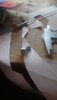
And here is the main body assembled with all parts made so far minus the valve.

The aircap wasn't anything special either. Just some drilling, boring and threading. It's got a 1.5mm hole in the front and a 1/8"BSP28 thread to thread onto the main body. On the side I put an M6 thread to connect the air to from the valve.


And this is what I got now minus the valve. I tested it with an old bike pump and at first it only bubbled up in the paintcup, but after moving the paint nozzle forward a bit, it sprayed water like it's supposed to. I'll now have to wait until I get my M2 hardware to attach the valve and get a compressor, but apart from the back cap and the spring for the needle, it's pretty much done now.

First, I started of making a drawing of how I'm making it. It's not on cardock, so it's not CAD, but PAD is fine for this. I changed the valve design around a bit from this drawing, but most other stuff is like it's on here. This isn't the current version of the design, but I don't have a current picture of it. I'll update it tomorrow.
I started off making the chuck for the needle. The needle is a 1.5mm knitting needle that I'll have to sharpen to get finer control, but it generally works.
It's just a 6mm piece of aluminium with a 1.5mm hole drilled through it and an M4 thread on the end with a 20° chamfer for the nut to press against and some slots cut in it with a fretsaw. The nut is just a piece of 6mm aluminium with an M4 thread not going all the way through.
The next thing I built was the valve. My valve doesn't offer very much control apart from on and off, but it works. It leaks a bit since I made on of the O-ring grooves a bit too deep, but that's not too difficult to fix if the general design works well.
I started off drilling and boring out the valve housing to get a 40mm deep flat bottom 12mm hole.
I used a makeshift boring bar made out of a piece of mild steel since I didn't want to grint down my HSS boring bar this much, but since it's just aluminium, it's fine.
Next up is the valve piston. I made this out of steel for no other reason than than I only have 12mm O-Rings and 12mm steel. I made the grooves with a cutoff tool, but I didn't grind it too well. Anyways, here it is.
I already attached the trigger in this picture, but I made that later. The valve assembly clamps around the rest of the gun, but I don't have the screws and tap for that yet.
After the valve and collet were working, I made the back portion of the main body. It's made out of 10mm aluminium. First, the inside was drilled out to 6mm 45mm deep and the end was threaded with a 1/8"BSP28 thread. After that, it got parted off because I needed to work on the other end of it.
This end first got center drilled with a 1.5mm hole and then reduced to 6mm.
After this, it got threaded with an M6 thread. I use the drill chuck in the tailstock to support the threading die holder to make sure the threads are straight.
Next, I had to make a slot into the tube for the trigger to go through. I did this by just drilling a few holes and connecting them since I don't have a mill.
After this, I made the front portion of the main body. I don't have any pictures of this, but it was pretty much the same, a bunch of drilling and threading. The only issues were a thread on an angle for the cup, but that worked out in the drillpress, and a bottomed out M6 thread. Since the Tap couldn't do blind hole threads, but an M6 screw with some flutes cut into it did the trick.
Next after this was the paint cup. I started with a piece of 19.5mm aluminium and first drilled it out to 10mm and then bored it out to 16mm.
After boring out the main part, I bored an angle into the angled portion of it using the top slide set to 36°.
Then, I parted it off again, flipped it around, drilled a 2mm hole into it for the paint to flow through and turned the outside taper onto it. After that, I threaded the thin part with an M4 thread.
And here is the main body assembled with all parts made so far minus the valve.
The aircap wasn't anything special either. Just some drilling, boring and threading. It's got a 1.5mm hole in the front and a 1/8"BSP28 thread to thread onto the main body. On the side I put an M6 thread to connect the air to from the valve.
And this is what I got now minus the valve. I tested it with an old bike pump and at first it only bubbled up in the paintcup, but after moving the paint nozzle forward a bit, it sprayed water like it's supposed to. I'll now have to wait until I get my M2 hardware to attach the valve and get a compressor, but apart from the back cap and the spring for the needle, it's pretty much done now.