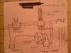
Okay, first off, I just realized that the cam and locking cam are backwards in this diagram :eek LOL, but yes, you got the idea. The only difference is that the travel will be 1-5/8" inch per trigger pull. Reason being is that the needles are 5 inches long (1/4" of the base of the spike will be recessed in the tube to help add stability) and I want them to be "spent" in three pulls. This will put the tip at 1/8" below the surface after the three pulls. At that point in time, the next trigger pull's current will be redirected to the next pair of spikes (one on each side).
So, to answer your question... There will be a mechanism (spring loaded arm) that stops and locks the locking cam from moving backwards. Kudus to you for seeing that part, and recognizing that would be an issue when it comes time to reload since I didn't even put that in the drawing!

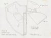
Like I stated before, the needles will drop down two at a time, until "spent". Starting from the back and outside, then moving to the inside, then to the middle outside, etc. I needed to make sure that the weapon could be reloaded at any point in time during this sequence. So, what will happen is, when the scope is tilted upwards to reload, this will pull all the needles into the "spent" position, regardless of their current position. Then, as the scope is returning back to its seated position, a mechanical catch will pull the spring loaded locking cam arms back to allow free movement in the reverse direction... thus allowing all the spikes to return to the fully loaded position.
Needless to say, some custom CNC milling will have to be done for a good portion of this, but I have some great leads on this