- Member DIN
- S097
Communication is difficult on the con floor, so why make it harder than it has to be.
The following guide will help you take an off-the-shelf pair of ear protection and adapt them to your helmet of choice. I first saw this technique used by PapaBraus on his MK VI helmet here: 3-D Printed MK VI helmet assembly and paint.
Thanks to NobleofDeath16 for peer pressuring me to write this tutorial, proofreading, and helping me take photos.
Disclaimers: This tutorial assumes/requires a basic competency in soldering and electronics. Even so, there is a possibility of damaging the circuit in following this tutorial, so proceed at your own risk. Be sure to read and understand this tutorial fully before starting work. Please be cautious when handling any glues, circuit components, or other materials inside the headphones. They may contain or be coated with harmful chemicals. It is recommended that you wear gloves and wash your hands after handling said materials. Work in a room with adequate ventilation and use a fume extractor or respirator when soldering.
The cheap circuit in the Zohan headphones picks up a lot of EMF, so expect to occasionally hear some noise (eg. when walking near a wireless router). Additionally, anything that vibrates your helmet, like fan noise, will be picked up by the microphones. All this to say- it's not perfect but it's better than nothing.
Parts:
22AWG Stranded wire, at least two colors
Zohan Headphones: Amazon.com
Battery Holder, 2xAAA: Amazon.com
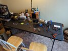
Tools:
Scissors
Small flathead screwdriver
Small Phillips screwdriver
Side cutters
Soldering Iron and solder
Solder sucker and/or solder wick
3rd hand
Wire strippers
Step 1: Disassemble the Headset
Remove the headset from the box.


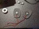
Remove the black earpads from each side. They are held in with small clips and should pop out with a light application of force. Save these for later.


Separate the earphones from the headband. Cut a slit along the top of the headband, making sure not to cut the cable inside. The headband can be discarded.


You should now have just the earphones connected by a black cable. Remove the battery door to get it out of the way.


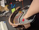
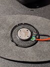
Take a small flathead screwdriver and slide it between the green plastic housing and the black plastic ring from which we removed the ear pads. Apply a gentle prying motion and they should separate. Save the black rings and foam pads, as we will use them to create the headphones for the inside of the helmet.
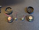
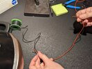
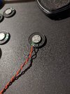
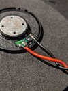
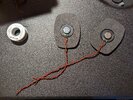
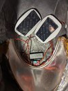
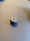
You should now be looking at the interior of the headphones. Remove the foam filler and discard it. With a small phillips head screwdriver, remove the speakers and the PCB (Printed Circuit Board). The electret microphones and 3.5mm jack are secured with an unidentified hot glue. Please use caution and I recommend gloves/wash your hands after handling unidentified glue. This can be peeled away, allowing the mics to be pulled out and the jack unscrewed. You will also want to remove the hot glue from around the circuit board, especially where it meets the volume knob. Side cutters can be extremely helpful for this, allowing you to use a pinch and twist motion. A flathead screwdriver can be useful as well. Be careful not to scrape or stab the PCB. Once you have removed the glue from around the PCB, it should slide out sideways. Save the knob to reuse, as the stem of the potentiometer can be difficult to turn. With your side cutters, cut away plastic to remove the cable from the plastic shell. If you haven’t already, remove the nut from the 3.5mm jack and pull it out of the shell. Cut the wire connections to the battery box.


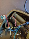
You should now have just the electronic “nervous system” of the headphones. If you don’t want to mess around with any custom wiring and the length of the premade wires works with your helmet you may attach the battery box and proceed to installation. Check all the wiring, especially the solder joints as they are often poorly connected and come loose during disassembly of the headphones. Resolder any broken wiring and skip to step 4. If you would like to clean u or extend the wiring, proceed to step 2.


Cont.
The following guide will help you take an off-the-shelf pair of ear protection and adapt them to your helmet of choice. I first saw this technique used by PapaBraus on his MK VI helmet here: 3-D Printed MK VI helmet assembly and paint.
Thanks to NobleofDeath16 for peer pressuring me to write this tutorial, proofreading, and helping me take photos.
Disclaimers: This tutorial assumes/requires a basic competency in soldering and electronics. Even so, there is a possibility of damaging the circuit in following this tutorial, so proceed at your own risk. Be sure to read and understand this tutorial fully before starting work. Please be cautious when handling any glues, circuit components, or other materials inside the headphones. They may contain or be coated with harmful chemicals. It is recommended that you wear gloves and wash your hands after handling said materials. Work in a room with adequate ventilation and use a fume extractor or respirator when soldering.
The cheap circuit in the Zohan headphones picks up a lot of EMF, so expect to occasionally hear some noise (eg. when walking near a wireless router). Additionally, anything that vibrates your helmet, like fan noise, will be picked up by the microphones. All this to say- it's not perfect but it's better than nothing.
Parts:
22AWG Stranded wire, at least two colors
Zohan Headphones: Amazon.com
Battery Holder, 2xAAA: Amazon.com
Tools:
Scissors
Small flathead screwdriver
Small Phillips screwdriver
Side cutters
Soldering Iron and solder
Solder sucker and/or solder wick
3rd hand
Wire strippers
Step 1: Disassemble the Headset
Remove the headset from the box.
Remove the black earpads from each side. They are held in with small clips and should pop out with a light application of force. Save these for later.
Separate the earphones from the headband. Cut a slit along the top of the headband, making sure not to cut the cable inside. The headband can be discarded.
You should now have just the earphones connected by a black cable. Remove the battery door to get it out of the way.
Take a small flathead screwdriver and slide it between the green plastic housing and the black plastic ring from which we removed the ear pads. Apply a gentle prying motion and they should separate. Save the black rings and foam pads, as we will use them to create the headphones for the inside of the helmet.
You should now be looking at the interior of the headphones. Remove the foam filler and discard it. With a small phillips head screwdriver, remove the speakers and the PCB (Printed Circuit Board). The electret microphones and 3.5mm jack are secured with an unidentified hot glue. Please use caution and I recommend gloves/wash your hands after handling unidentified glue. This can be peeled away, allowing the mics to be pulled out and the jack unscrewed. You will also want to remove the hot glue from around the circuit board, especially where it meets the volume knob. Side cutters can be extremely helpful for this, allowing you to use a pinch and twist motion. A flathead screwdriver can be useful as well. Be careful not to scrape or stab the PCB. Once you have removed the glue from around the PCB, it should slide out sideways. Save the knob to reuse, as the stem of the potentiometer can be difficult to turn. With your side cutters, cut away plastic to remove the cable from the plastic shell. If you haven’t already, remove the nut from the 3.5mm jack and pull it out of the shell. Cut the wire connections to the battery box.
You should now have just the electronic “nervous system” of the headphones. If you don’t want to mess around with any custom wiring and the length of the premade wires works with your helmet you may attach the battery box and proceed to installation. Check all the wiring, especially the solder joints as they are often poorly connected and come loose during disassembly of the headphones. Resolder any broken wiring and skip to step 4. If you would like to clean u or extend the wiring, proceed to step 2.
Cont.
Attachments
Last edited: