SirPalesAlot’s MK VI WIP: You’re still not done yet?

Status
Not open for further replies.
Hey…I recognize that! That's the pain in the…arm…that I've been working on for the last week doing it from scratch instead of from somebody's "here ya go!" pep file! (Actually, the lower line which you haven't added yet is even more a pain in the…arm.)

Looking good. (In that photo it kind'a looks like the right side of the ridged line is too low? And the angles at the indent's bottom should be a little steeper.)

That line wasn't too difficult to add, but the other one might prove to be annoying lol. I just wish I could scratch build things, but I'm horrible at it lol. In the screenshot I took the model looks like its rotated a bit which is why the lines look a bit unlevel. I made the changes to the angles on the indented detail. I think this looks a bit better.

Forearm_Back_Detail_2_zpsde9becd0.png
 

Attachments

  • Forearm_Back_Detail_2_zpsde9becd0.png
    Forearm_Back_Detail_2_zpsde9becd0.png
    14 KB · Views: 167
They still look like 45° and should be more like 60°. I had to really study multiple photos to even confirm that the corners were indeed angled at all rather than just seeming that way from shadows. Keep it if you like it, but from my perspective the angles looked steeper in photos (I went with 30° at the top and 60° at the bottom). Even though some of my own pep photos look like 45° corners, it's just from the photo angles and you can see in my thread post #146 that mine were made steeper than they seem in other photos.

The lower line is a lot more than "annoying". lol

I wish I had your forearm file before starting on all my scratchbuilding customizations. Keep up the great work!
 
That line wasn't too difficult to add, but the other one might prove to be annoying lol. I just wish I could scratch build things, but I'm horrible at it lol. In the screenshot I took the model looks like its rotated a bit which is why the lines look a bit unlevel. I made the changes to the angles on the indented detail. I think this looks a bit better.

Forearm_Back_Detail_2_zpsde9becd0.png

Looking forward to building these for my halo armor when they are finished.
 

Attachments

  • Forearm_Back_Detail_2_zpsde9becd0.png
    Forearm_Back_Detail_2_zpsde9becd0.png
    14 KB · Views: 168
They still look like 45° and should be more like 60°. I had to really study multiple photos to even confirm that the corners were indeed angled at all rather than just seeming that way from shadows. Keep it if you like it, but from my perspective the angles looked steeper in photos (I went with 30° at the top and 60° at the bottom). Even though some of my own pep photos look like 45° corners, it's just from the photo angles and you can see in my thread post #146 that mine were made steeper than they seem in other photos.

The lower line is a lot more than "annoying". lol

I wish I had your forearm file before starting on all my scratchbuilding customizations. Keep up the great work!


Now Im getting confused. I'm not sure if we are talking about the same things anymore lol. I checked the angles on the detail just to see what they were and this is what they came up to be. Which one of the two angles needed to be changed? Forearm_Back_Detail_3_zpsc5d6b488.png

Yeah I just tried to start on that lower line and the transition from the back to the sides sucks. I could easily make something like that with the software I use at work, but it isn't compatible with Pepakura Designer.
 

Attachments

  • Forearm_Back_Detail_3_zpsc5d6b488.png
    Forearm_Back_Detail_3_zpsc5d6b488.png
    135.8 KB · Views: 164
You don't need to change anything if you don't want to. The angles I'm referring to which don't look steep enough (in my opinion) are at the base of the "indented detail". Where you have 53° should actually be steeper (more vertical) than the angles of the large "V" (which now looks too steep on the sides at 61°). Here's a photo that shows the two angles pretty well:

Reference2.jpg


I totally agree about the lower line transition from front to back. Mine doesn't exactly match photos, but after a week of sketching out the line and not being able to match all the angles as seen in photos I simply drew something in that represents it decently and moved on with the build. The problem I had is, to have it in (about) the proper vertical position on the inside, there wasn't enough room on the sides for it to angle downwards before curving back up to the notched recessed crescent's corners. Move the line higher to have room for the downwards angles and it looked too close to the indented detail. Having it the right space from the indented detail and the side curves end up being way too steep for reaching the crescent's corners. So I had to compromise on the transition, and it looks "okay" from different views (especially when no photos are around to compare against!).
 

Attachments

  • Reference2.jpg
    Reference2.jpg
    5.3 KB · Views: 140
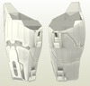
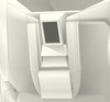
So, after I tried adding the lower recessed line the other day I came to the conclusion that it wasn't going to work. I just felt like the surface of the model wasn't smooth enough to make that line possible. I could have thrown something on there, but it wouldn't have looked good. If the model were smoother then it would be much easier to make this line. After I came to that conclusion I decided to remake the entire main body of the forearm. I tried to do this last year and I failed. This time I was successful. Here is the forearm with the new smooth main body. The outer profiles in X0 and Y0 are the same as the original even if they don't seem that way. I still have to add back all of the detail I added in the last attempt, but that shouldn't be as hard now.

Forearm_Remake_1_zps0b783517.png


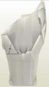
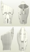
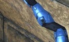
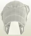
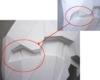
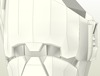
The back detail has been a bit of an issue. After thinking about it for quite a while I have come to the conclusion that the detail on the back is actually raised and not recessed. In the pictures below you will see a few red lines running parallel to what appears to be angled walls on the forearm. If those objects are in fact angled walls then it would mean that area is raised. At the perspective those parts are being viewed from you would not be able to see the wall if it were recessed. Since you can see it then it means it must be raised. Also, in the lowest picture you can see light shining on that same wall. If that area were recessed then there would be a shadow cast in that area.

Forearm_Back_Detail_6_zps08488c63.png

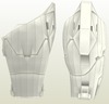
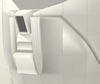
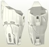
The angles of the lines on the back detail have been a bit of a pain. In the picture below you can see a pretty clean view of these lines.
Forearm_Back_Detail_5_zps12e03137.png


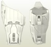
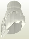
In the reference pictures it appears that the angled lines are equal distances away from the detail on each side. When I try to add in this detail (while holding all distances and angles at center) I end up with the distance away from the part being uneven. This bugs me quite a bit. I know that the small notch is on center of the back. I have been torn between whether the angles were actually different to allow for the lines to be equal distances away from their detail, or if the distances away from their detail were actually different sizes but not represented well in pictures.


In this picture I have all the lines on each side at the same angle with the detail on center of the back. You can see that the distance they end up away from the part is uneven.

Forearm_Back_Detail_7_zps9ea99b21.png


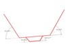
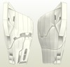
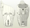
I took that screencap from before and I put lines over the details and then dimensioned them. Although there is no way to be really accurate with placement (lack of points to snap to, and texture issues) I think there is enough of a difference in two of these angles to believe that one may actually be different than the other. This would allow for the angles to appear close to the same when on the part, and it would also allow for the distances away to be close to the same as well. You can see the dimensioned version below.

Forearm_Back_Detail_4_zps2914d80b.png

I will still probably keep the angles on the small notch the same on each side, but I will probably make the two larger lines different. The key will be making the angles different enough to make the distances away from the part appear to be the same while still giving off the appearance of having the same angle.


Regardless, I still have to add the detail back to the front first so that gives me some time to get some input from everyone. I also plan to scale the model closer to the size I am going to use so I can check the height/depth of all the detail that I am adding. If I find some areas to be too small I may bump them up to the nearest 1/8th of an inch just to give them a little bit more presence. This will also make the detail easier to build.
 

Attachments

  • Forearm_Remake_1_zps0b783517.png
    Forearm_Remake_1_zps0b783517.png
    455.8 KB · Views: 156
  • Forearm_Back_Detail_6_zps08488c63.png
    Forearm_Back_Detail_6_zps08488c63.png
    1,013.3 KB · Views: 165
  • Forearm_Back_Detail_4_zps2914d80b.png
    Forearm_Back_Detail_4_zps2914d80b.png
    13.5 KB · Views: 170
  • Forearm_Back_Detail_7_zps9ea99b21.png
    Forearm_Back_Detail_7_zps9ea99b21.png
    14 KB · Views: 167
  • Forearm_Back_Detail_5_zps12e03137.png
    Forearm_Back_Detail_5_zps12e03137.png
    425.5 KB · Views: 185
Well, when I look at the angled lines in every photo I see of them, including the ones you posted (especially in that last "red" one), it looks very much to me like they're recessed towards the top rather than raised. This is especially true when examining photos and the 3D geometry of how the front detail interacts with the line on the inside edge. If you look at the other arm than the one you marked up in the "green" photos, the line even looks like it's scribed rather than ridged. At first that's how I thought this line was but I just wasn't able to resolve a clear difference in height of the front detail piece until close inspection of photos revealed a stepped line rather than etched, and that was the missing ingredient to getting the shapes to all line up. If you look at the upper-right and center-right reference photos of the 3D model photo in my detail piece thread (3rd photo from the top of the thread), you can very clearly see that this line is stepped with the upper portion recessed (the shadows are a dead giveaway). These same shadows also exist on the same side in your "white" armor photo and the last "red" photo. I think the "green" ones are just rendering aberrations and like Carpathia has also mentioned - you can't take any one single photo as "gospel". Cross-reference across several photos from different sources to get driven really crazy by all the conflicting appearance of details. I'm just about finished with both my forearm pieces and the way ambient light interacts with the angled line has it looking just like the photos in my opinion.

As for the angles of the lines, I didn't even measure them in my own build. I highly doubt they're symmetric even though they look like it in photos. I eyeballed the horizontal segment lengths and then just sketched in the angled segments to "connect the dots". The angles on my notched detail are the same on both sides. When I compare the pep to photos, it looks pretty darned close to matching.

After looking at some more photos I’m beginning to think the area may not be raised or recessed, and the detail is nothing more than a trench. In the views I posted before the area appears to be raised (to me), but the views you referred to in your detail thread clearly show a shadow on the correct side for it to be recessed. Since those images go against what I was seeing in the images I posted, I decided to do some more digging. I went to the screenshot gallery on Halo.Bungie.net and scanned through about 300 of the pages before I finally called it quits. Here are all the good views of the forearm I could find during that time.


Forearm_Detail_6_zps90cfb0cd.jpg
Forearm_Detail_5_zpsa9757c25.jpg
Forearm_Detail_9_zps43140187.jpg
Forearm_Detail_8_zps830fea21.jpg
Forearm_Detail_7_zps25d87248.jpg
Forearm_Detail_4_zps6db3cfc3.jpg
Forearm_Detail_3_zps455871bc.jpg
Forearm_Detail_11_zps8b87834e.jpg
Forearm_Detail_13_zps96b4b9a2.jpg
Forearm_Detail_1_zps55373e05.jpg
Forearm_Detail_10_zps357ada11.jpg
Forearm_Detail_2_zps02681f34.jpg
Forearm_Detail_12_zpsf47ce3ed.jpg


Based on these images I think it may be best to leave the detail as a trench because the images constantly contradict themselves. Some areas appear raised, some appear recessed, and in most of them it appears to be the same height. There are some instances where both forearms are shown and the detail is different from the right to left versions. The area as you have it looks good recessed, but the raised version I worked up also looks good as well. Since I can’t really pick one over the other I will just settle for the in between version just to be safe. Also, if you want some extra hi-res screenshots you can browse through this gallery. There are a lot of images that can be put to good use. I found a really good image of the detail around the back side of the neck seal.

I managed to re-work the angles and I think I only have a 5 degree difference from one side to the next and most of my distances stay close to the same. The 5 degrees isn’t really noticeable when the lines are flat, and I’m sure it would be harder to see the difference once that is wrapped around the curve of the main body.


I was going to make a joke about that spam comment, but it seems to be gone already.
 

Attachments

  • Forearm_Detail_7_zps25d87248.jpg
    Forearm_Detail_7_zps25d87248.jpg
    86.8 KB · Views: 150
  • Forearm_Detail_9_zps43140187.jpg
    Forearm_Detail_9_zps43140187.jpg
    136.5 KB · Views: 142
  • Forearm_Detail_5_zpsa9757c25.jpg
    Forearm_Detail_5_zpsa9757c25.jpg
    126.9 KB · Views: 150
  • Forearm_Detail_6_zps90cfb0cd.jpg
    Forearm_Detail_6_zps90cfb0cd.jpg
    135.5 KB · Views: 134
  • Forearm_Detail_11_zps8b87834e.jpg
    Forearm_Detail_11_zps8b87834e.jpg
    61.9 KB · Views: 158
  • Forearm_Detail_3_zps455871bc.jpg
    Forearm_Detail_3_zps455871bc.jpg
    117 KB · Views: 144
  • Forearm_Detail_4_zps6db3cfc3.jpg
    Forearm_Detail_4_zps6db3cfc3.jpg
    109.8 KB · Views: 142
  • Forearm_Detail_13_zps96b4b9a2.jpg
    Forearm_Detail_13_zps96b4b9a2.jpg
    81.5 KB · Views: 141
  • Forearm_Detail_1_zps55373e05.jpg
    Forearm_Detail_1_zps55373e05.jpg
    148.3 KB · Views: 140
  • Forearm_Detail_10_zps357ada11.jpg
    Forearm_Detail_10_zps357ada11.jpg
    149.2 KB · Views: 145
  • Forearm_Detail_2_zps02681f34.jpg
    Forearm_Detail_2_zps02681f34.jpg
    128 KB · Views: 144
  • Forearm_Detail_12_zpsf47ce3ed.jpg
    Forearm_Detail_12_zpsf47ce3ed.jpg
    63.4 KB · Views: 140
I was staring at this in forge and after approaching ever angle and many light sources. I am in agreement it definitely looks like a trench.

Gamertag: RYNOx666
 
...because the images constantly contradict themselves...There are some instances where both forearms are shown and the detail is different from the right to left versions.

Exactly. Different images constantly contradict themselves. That's why ultimately it comes down to the builder's decision of how they want their armor to look. If somebody says, "hey, you didn't make that right", well, "right" is a totally subjective term in this case. Somebody can show me a photo of that line and in that particular photo I will agree and say, "yep - that sure does look like a trenched line". But then I can pull out a photo of my own and show that very same line being clearly stepped rather than trenched and say, "see, it is 'right' according to this photo".

I totally agree that in many photos the line does look trenched and that's how I was originally going to pep it. But I couldn't resolve the unevenness in height at the antecubital detail until I saw other photos with the line stepped rather than trenched, so I went with stepped since it's "right" for some photos and fixed the issues I was having with the detail piece. If I had seen these photos earlier, I would have pepped it as a trench - in fact, I'm now seriously considering modifying my pep to turn it into a trench…. (damn…)


Edit: So, when this trenched line crosses across the notched indented area, I again see conflicting photos - some show the line as straight across the indent, and others show the line bending to follow the angled bottom edge of the indent. What's your consensus of how the trenched line passes through the indent in the center? I'm leaning towards following the edge since that's how it looks in most of the photos.
 
I think the detail is on a contour plane. This could be the the reason the light sources interact differently to it. Trench it. :-D

Gamertag: RYNOx666
 
Okay, here are my conclusions after looking through a lot more photos. The angled inside line is indeed trenched rather than stepped (I've already started modifying my parts), the line follows the bottom three edges of the center notched indent as it passes through it (which is deeper than I originally pepped it, so I'm doubling the mat board thickness of the indent's cutout), the bottom three sides of the notched indent (horizontal and two angled segments) are slanted inwards toward the indent rather than perpendicular to the arm surfaces (I'll get that detail later with Bondo), and the antecubital detail I modeled doesn't seem wide enough. My original depth of 50 is fine, but the width should be more like 30 instead of 27 (yeah, those 3mm make a difference at my scale). I'm not changing it now on mine, but thought you might want to know for widening this detail on your model. The front edge should stay fixed and the width should increase from the opposite side. You've also corrected something else in your model that I'm just now seeing from these new photos, and I've modified my pep for this as well - there is no "rim" on the top front and instead the arm opening is all the way to the detail piece. You're going to have a very fine set of pdo files once you've finished.
 
Okay, here are my conclusions after looking through a lot more photos. The angled inside line is indeed trenched rather than stepped (I've already started modifying my parts), the line follows the bottom three edges of the center notched indent as it passes through it (which is deeper than I originally pepped it, so I'm doubling the mat board thickness of the indent's cutout), the bottom three sides of the notched indent (horizontal and two angled segments) are slanted inwards toward the indent rather than perpendicular to the arm surfaces (I'll get that detail later with Bondo), and the antecubital detail I modeled doesn't seem wide enough. My original depth of 50 is fine, but the width should be more like 30 instead of 27 (yeah, those 3mm make a difference at my scale). I'm not changing it now on mine, but thought you might want to know for widening this detail on your model. The front edge should stay fixed and the width should increase from the opposite side. You've also corrected something else in your model that I'm just now seeing from these new photos, and I've modified my pep for this as well - there is no "rim" on the top front and instead the arm opening is all the way to the detail piece. You're going to have a very fine set of pdo files once you've finished.


That inner detail did seem a bit undersized compared to the rest of the model. I noticed after looking at all those reference pictures that it wasn't the right length, but I hadn't considered the width.

I'm not sure if I understood all that you described there (sometimes it's hard to follow things without a image to reference), but I went ahead and modeled up what I thought you were talking about. Also, you will notice the bottom end of this model has been extended past where I had it previously. This was added in just to make it easier to add supports, and the end can be trimmed back to whatever angle/length someone might see fit.

Forearm_Detail_14_zps1dfbc7ba.png
Forearm_Detail_15_zps4e2949d0.png
Forearm_Detail_16_zpsf2868ac0.png
Forearm_Detail_17_zpsea6157d9.png

I also thought I would get two more views to show how the trench line could be mistaken for a raised or recessed area. If the shading were poor in these pictures I think it might look much closer to what we kept seeing in the images.


Forearm_Detail_18_zps447e72a7.png
Forearm_Detail_19_zpsde68a4f3.png
 

Attachments

  • Forearm_Detail_14_zps1dfbc7ba.png
    Forearm_Detail_14_zps1dfbc7ba.png
    290.3 KB · Views: 152
  • Forearm_Detail_17_zpsea6157d9.png
    Forearm_Detail_17_zpsea6157d9.png
    215 KB · Views: 167
  • Forearm_Detail_15_zps4e2949d0.png
    Forearm_Detail_15_zps4e2949d0.png
    350.1 KB · Views: 160
  • Forearm_Detail_16_zpsf2868ac0.png
    Forearm_Detail_16_zpsf2868ac0.png
    202.4 KB · Views: 154
  • Forearm_Detail_18_zps447e72a7.png
    Forearm_Detail_18_zps447e72a7.png
    168.8 KB · Views: 166
  • Forearm_Detail_19_zpsde68a4f3.png
    Forearm_Detail_19_zpsde68a4f3.png
    123.2 KB · Views: 164
You've nailed the lines - it looks awesome and I wish I had this pep file two months ago! The length of my detail piece is correct (well, maybe it's a tiny bit too long) - it spans to the crescent's notch just like you have it in your model (you have to remember my model is sized differently than yours). After looking at your reference pictures, though, it appears I've modeled the detail too narrow. It looks wider in the photos and mine is too rectangular (tall in the y-direction). I plan on releasing an updated pdo with the width stretched to correct the shape. (I did also notice a couple other aspects from your photos that I didn't get modeled quite right - my references weren't as good as yours - but I'm not planning to remodel them.) If I had that forearm model and was as fluent with mesh modeling as you seem to be, I'd widen the antecubital detail towards the angled trenched line so it looks more like the photos. Very noticeable in this one (but in others as well):

Forearm_Detail_9_zps43140187.jpg


Here's something else to consider for the top of the detail from what I'm seeing in your reference photos:

top.jpg


It's just a quick sketch to show how the raised surface looks to me relative to the recessed areas. I couldn't get the width of the trench the same because either you drew the trench lines too wide (path width) or I drew the sides of the detail area too tall. But it kind've looks like this to me in your Detail 1, 7 and 9 photos.


What I meant by the notched indent (the one at the bottom of the V trenched line) is it looks in the photos like the "walls" of the bottom aren't vertical, but rather slanted inwards (so the outer forearm surface has a larger perimeter than the floor of the indented detail) but only on the bottom three sides (the bottom horizontal and its two adjacent angles to the verticals). Then, the trenched line continues through this detail rather than stopping at its sides and follows the bottom contour, like in this photo:

Forearm_Detail_7_zps25d87248.jpg


Now, if you really want to get it perfect, the lateral terminating notches of the front/side recessed crescent don't have the correct shape. The forward angle of these notches is very obtuse with the protruding notch having a narrower bottom than the rest:

Gauntlets4.png


Any plans on adding the recessed lines inside the recessed crescent?

You make me want to start over on the forearms using your model instead of the one in the database. But, me thinks that if I keep starting over on the same pieces I won't get it completed by Autumn 2014. I'll probably download the pdo anyway once you're finished with it to have it in my files collection in case I end up building another costume sometime. Excellent work.
 

Attachments

  • Forearm_Detail_9_zps43140187.jpg
    Forearm_Detail_9_zps43140187.jpg
    136.5 KB · Views: 134
  • top.jpg
    top.jpg
    4.2 KB · Views: 129
  • Forearm_Detail_7_zps25d87248.jpg
    Forearm_Detail_7_zps25d87248.jpg
    86.8 KB · Views: 130
  • Gauntlets4.png
    Gauntlets4.png
    503.8 KB · Views: 153
You've nailed the lines - it looks awesome and I wish I had this pep file two months ago! The length of my detail piece is correct (well, maybe it's a tiny bit too long) - it spans to the crescent's notch just like you have it in your model (you have to remember my model is sized differently than yours). After looking at your reference pictures, though, it appears I've modeled the detail too narrow. It looks wider in the photos and mine is too rectangular (tall in the y-direction). I plan on releasing an updated pdo with the width stretched to correct the shape. (I did also notice a couple other aspects from your photos that I didn't get modeled quite right - my references weren't as good as yours - but I'm not planning to remodel them.) If I had that forearm model and was as fluent with mesh modeling as you seem to be, I'd widen the antecubital detail towards the angled trenched line so it looks more like the photos. Very noticeable in this one (but in others as well):


Here's something else to consider for the top of the detail from what I'm seeing in your reference photos:


It's just a quick sketch to show how the raised surface looks to me relative to the recessed areas. I couldn't get the width of the trench the same because either you drew the trench lines too wide (path width) or I drew the sides of the detail area too tall. But it kind've looks like this to me in your Detail 1, 7 and 9 photos.


What I meant by the notched indent (the one at the bottom of the V trenched line) is it looks in the photos like the "walls" of the bottom aren't vertical, but rather slanted inwards (so the outer forearm surface has a larger perimeter than the floor of the indented detail) but only on the bottom three sides (the bottom horizontal and its two adjacent angles to the verticals). Then, the trenched line continues through this detail rather than stopping at its sides and follows the bottom contour, like in this photo:


Now, if you really want to get it perfect, the lateral terminating notches of the front/side recessed crescent don't have the correct shape. The forward angle of these notches is very obtuse with the protruding notch having a narrower bottom than the rest:

Any plans on adding the recessed lines inside the recessed crescent?

You make me want to start over on the forearms using your model instead of the one in the database. But, me thinks that if I keep starting over on the same pieces I won't get it completed by Autumn 2014. I'll probably download the pdo anyway once you're finished with it to have it in my files collection in case I end up building another costume sometime. Excellent work.


I wish I would have had these files a long time ago as well lol. I spent so much time remaking the forearm last year, and I settled for less than I was capable of because I didn't "think" I could actually do it. If I had went through that screenshot gallery a long time ago I might have already tried to model in some of that detail, but back then I was still in the "good enough" kind of mood. After seeing what you did with your models it got me fired up enough to want to do more. I would just feel kind of disappointed with myself if I didn't try to make this the best I could. So I really do have to thank you for giving me the push to do more.


I was pretty bad at mesh modeling, but after I learned the basics from the software it's only a matter of taking my ideas and putting them on screen. It all gets easier the more you do it. If you're pretty good at learning software I would say try out Google Sketchup and Blender. I usually do my base modeling in Sketchup, and then I clean up the triangles (turning triangles to quads) and vertices in Blender. I still can't model something from scratch based only on images, but I'm getting better at modeling detail from images so it's a start. Most of my expreience in modeling comes from software that uses NURB surfaces. I'm also spoiled by having actual drawings as well. Making models in this way using mesh modeling is still strange to me.


I think when I imported the detail originally that it may have been scaled incorrectly, but I think the proportions I have it at right now look pretty good compared to the rest of the model. Right now the detail is the exact same width as the detail at the bottom of the forearm. I could probably get away with increasing the width, but it would probably have to go towards the front. If I extend it anymore towards the back it changes the angled lines, and it becomes hard to attach to the main body. That inner detail does look as if it's a bit closer to the crescent shape than I have it so adding the thickness to that side would probably help that look more correct.


You will notice in the photos that I intersected the trench with the inner detail piece so it more closely matches the pictures. I also changed the shapes at the top to better match what you sketched up. I think this matches enough to pass. The width of the trench at my scale is only 0.187.

Forearm_Detail_22_zps35763987.png
Forearm_Detail_23_zps04b396cf.png


You can also see that I went back and changed the angle on the notches in the crescent shape, and I also added the small trenches. I was going to leave the trenches out, but I thought I might as well go all the way with it so I wont have to fool with it later. Since I plan on building the full detail versions of all the files anything I add in helps me out down the road anyways. The small trenches are 0.063 at my scale. I didn't bother to round them out because they are so small. I thought that a V shape would be a good enough start to work with in the later stages.

Forearm_Detail_21_zpsc8d1a5e7.png
Forearm_Detail_20_zps602723c0.png


Let me know what you think. As soon as I get all the details ironed out I can start unfolding. As with the last set of files I released there will be three different versions. The MD version will include all of the major changes, no recessed trenches, and a simpler version of the inner detail. The HD version will included all of the major changes, the fixed recessed detail, a simpler version of the inner detail, and no trench detail on the back. The FD version will include everything. I don't think this piece needs a LD version or a test file since there are many other files out there that can accomplish that pretty well.
 

Attachments

  • Forearm_Detail_22_zps35763987.png
    Forearm_Detail_22_zps35763987.png
    213.8 KB · Views: 137
  • Forearm_Detail_21_zpsc8d1a5e7.png
    Forearm_Detail_21_zpsc8d1a5e7.png
    284.3 KB · Views: 164
  • Forearm_Detail_23_zps04b396cf.png
    Forearm_Detail_23_zps04b396cf.png
    177.7 KB · Views: 136
  • Forearm_Detail_20_zps602723c0.png
    Forearm_Detail_20_zps602723c0.png
    361 KB · Views: 139
They look fantastic now! The detail at the top looks way better. There's now only one more thing I'd revise for a "perfect" forearm (excluding the inaccuracy in the interior of my detail part). The two "upside down T" details at the bottom of the forearm look like you've sloped the sides too much resulting in the tops being too small. These tops should be large enough to support a domed shape in their centers (and these domes have a circular recess at their tops). I don't recommend modeling the domes, but the flat tops of these details should be larger to support adding the domes if a builder chooses to (I'll be adding these domes during detailing of my armor). You can see what I'm talking about in the "red" photo from post #94. Aside from that, or if anybody else has suggestions, I think they turned out awesome. (Now I'm feeling like the baker who made a cake from scratch, and then out comes a pre-fabricated "just a water" mix. Oh well…)
 
I absolutely love how much detail youre putting into parts. Im going to absolutely HATE building it with all the tiny flaps and such but it will look absolutely stunning to see someone build this. I cant wait for the release.
 
They look fantastic now! The detail at the top looks way better. There's now only one more thing I'd revise for a "perfect" forearm (excluding the inaccuracy in the interior of my detail part). The two "upside down T" details at the bottom of the forearm look like you've sloped the sides too much resulting in the tops being too small. These tops should be large enough to support a domed shape in their centers (and these domes have a circular recess at their tops). I don't recommend modeling the domes, but the flat tops of these details should be larger to support adding the domes if a builder chooses to (I'll be adding these domes during detailing of my armor). You can see what I'm talking about in the "red" photo from post #94. Aside from that, or if anybody else has suggestions, I think they turned out awesome. (Now I'm feeling like the baker who made a cake from scratch, and then out comes a pre-fabricated "just a water" mix. Oh well…)


Yeah I thought those shapes looked a bit off, but I was going to leave them. I only made slight adjustments to them originally, and it didn't take much away from the area where that dome shape goes. After looking at that area a bit more it seemed like the angles for the side walls were suppose to continue up the entire shape. I also noticed that the detail should have been more narrow than it was. I went back and made those adjustments to that detail piece, and I adjusted the width of the upper detail piece. From the side view the lower detail appears as if it sticks out farther than it should, but the outer most flat is exactly the same distance away.


Forearm_Detail_24_zps6628e789.png


I absolutely love how much detail youre putting into parts. Im going to absolutely HATE building it with all the tiny flaps and such but it will look absolutely stunning to see someone build this. I cant wait for the release.

Thank you! I have a feeling these parts are going to make me very angry, but I will just have to remind myself that it will save time down the road. As soon as I get the details ironed out it shouldn't take long to create the unfolds.


Looking ahead to my next part I am thinking of taking on the helmet. I think I am going to remove all of the extra detail I added and go for in game accuracy rather than adding all the detail I can find from the other versions. This just seems to make more sense because all the other parts are detailed according to in game references. A member of Stony Props already recreated the Halo 3 in game helmet and 3D printed it, and I will probably use images of that to make changes to my model. I thought about buying one of those helmets because it is probably as close to perfect as you could get, but then I couldn't say that I made it myself. I at least want my first full suit to be something I made myself.


Let me know what you guys think. Thanks for stopping by!
 

Attachments

  • Forearm_Detail_24_zps6628e789.png
    Forearm_Detail_24_zps6628e789.png
    397.2 KB · Views: 151
You know if you think about it once you put together all the parts then mold them you could make just one set of armor. Them have all the mutations clip onto your build so you wouldnt have to make them over and over.
 
You know if you think about it once you put together all the parts then mold them you could make just one set of armor. Them have all the mutations clip onto your build so you wouldnt have to make them over and over.


I actually thought of that as I was going through the gallery of screenshots the other day. It would be pretty easy to rig up a system to interchange the pieces for the shoulder and torso, but you would still need multiple helmets. I think the best time to do it would be at this part of the process. I would have to make the model for the shoulders and torso with that in mind and make sure the other attachments would fit whatever setup I created. As of right now I only plan to do the standard MK VI, but if I did decided I wanted another variant that is the way I would go.
 
Status
Not open for further replies.
Back
Top