Props Needler Multimedia Arduino-Driven Animated Airsoft Prop (Everything the Neca Needler Could Have Been)

This update is focused on the nose area and looking ahead to the mods needed to not only hide the airsoft components in here, but be able to access and service them post construction. We have already seen that there is not a lot of front to back space to install components. There are also width concerns as well.

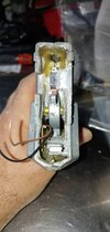
Starting at the bottom, there is not a lot of room for electronics and the air hose to pass up to the cylinder chamber and barrel. After taking a look, I determined that although it is pretty tight, there is enough room here.

20200217_221446.jpg

View from the underside looking up. The gap at the top of the photo is where the air hose and electronics harness will access the actual firing components. The area at the bottom of the picture is where the regulator (attached to the high-pressure air bottle) will occupy. The battery and Arduino components will likely also reside in this space as it is the only significant space not already taken.

Viewed from above, the narrowness of the channel is apparent. So is the awfulness of the seams. These will go away as this becomes a one-piece assembly. The struts and pegs for screws will go away as well to give more space.


20200217_221548.jpg

View of the bottom section from above. The halves will be bonded together permanently and strengthened.

There is a cluster of seven lights that dominated the space and the back of the center section. This was very effectively glued on by NECA. I'll need this to remain removable in the future as it will give the best access to the back end of the airsoft components including the air hose attachment. I will probably use just magnets to hold the light cluster in place.

20200217_221536.jpg

A view from the back of the nose section. the narrowest point is too small for the airsoft components so I will have to widen it slightly. The slot at the bottom on the photo is where the pistol grip attaches to the lower section. This will become a permanent attachment and strengthened as this was a major source of flex and noise as originally constructed.

The front of the nose piece shows the massive gaps at the seams and the inconsistent depth of the molded details. It won't be hard to improve the look of this area. Once joined into a single piece and the seams filled, I'll sandblast it all and coat it with a slurry of epoxy and aluminum powder that will be buffed into a polished metal surface that is tough enough to not chip even when struck by high-velocity BBs.

20200217_221604.jpg

View from the front. Lots of seams to be eliminated and details to be sharpened.

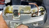
With the nose section apart, more hot glue is the theme. The tininess of the space is very evident. The diamond-shaped area will need to be removable to access the hop-up adjustment and barrel mechanics. The rat's nest of wires will need to be cleaned up as the LEDs are converted to pink.

20200221_141002_HDR.jpg

Left side of the nose assembly. The first modification will be to cut away the diamond-shaped area.

In order to preserve the spatial relationship of the upper and lower components while the emitter area is cut away, I glued in strips of styrene. This whole area will need to be subtly-widened at the rear to accommodate the width of the cylinder. All pegs for screws will be eliminated when the halves are fiberglassed together.

20200221_132151_HDR.jpg

Styrene strips to hold components in alignment after cuts are made.

I got really busy with the Dremel saw and cut away the emitter section and the side walls of the nose section. This will allow me to widen the area slightly by moving the side walls outward. The emitter section halves will be joined and will be removable to permit servicing airsoft and electronics components inside.

20200221_155736_HDR~3A.jpg

Horrid picture of the sad remains of the emitter section. No going back now!

Most of the major disassembly is behind me know. Here is what the state of the disassembled components looks like now. Notice how many components are not broken along their factory seams.

20200221_155736_HDR~3.jpg


20200221_155720_HDR~3.jpg

Pretty cool display of all the parts. A lot of work to get to this point. And a lot of planning.

Next up: Final disassembly. I'm excited to turn the corner from disassembly to construction.

Redshirt

Guess who's not coming back from the Slayer match--the guy in the Red Shirt
Signature Project: Halo 3 Working Airsoft Spartan Laser in Metal & Fiberglass
 
Update time.
Final disassembly. Happy to reach this point and start full-time imagineering.

So first up is the pistol grip section, source of many squeaks, rattles and the toy-like feeling of the original prop. Like a car with a wrong-feeling steering wheel. The trigger moves most of an inch to shoot and is super spongy. No wonder. It appears they used the spring from a ball point pen to work it. It is the wrong shape to the game gun so it gets replaced by something smaller, firmer and with a crisp break.


20200328_153031_HDR.jpg

The inside of the pistol grip showing trigger assembly.

The reload switch is also inside the pistol grip. This actually has a pretty tidy installation that works well. It is probably the only feature I'll keep unchanged. Of course in the future it will be communicating with the Arduino rather than the factory electronics.

So I do have some serious challenges with the pistol grip area. Like I said, it is weak and squeaky. I plan to line the inside with fiberglass and fiberglass the halves together. I will then permanently bond the grip to the upper and lower portions of the spaceframe. that means that I have to design the trigger and reload switches to be able to be serviced from the small opening that will be at the top.

20200328_152926_HDR.jpg

Small board for the reload switch.

At this point all that is left in the upper housing are a few stray electronic components. I plan to cover as much as possible of the inside with fiberglass mat to strengthen it and join pieces together permanently. To do that I'm going to need to remove quite a few screw moldings and other features.

20200328_152821_HDR.jpg

Hot glued (and detached, naturally) blue LED board for side lights. Opening on the right side bottom is where the pistol grip attaches. I will run stips of fiberglass through there to permanently bond the grip to the upper housing.

All the way to the rear of the upper housing lies a tiny 0.5 watt speaker that has been asked to do too much, resulting in fairly distorted sound effects. The plan: fiberglass this area smooth then have my CNC milling machine drill hundreds of tiny and nearly invisible holes for the new speakers, a pair of 5 watt jobs. I have an amp coming to make sure I can get the best quality and best volume from them. Spartan Jess has already pulled and cleaned outstanding sound files from the H2A needler. The end result will be miles ahead of the original sound system.

20200328_152825_HDR.jpg

I didn't know you could get a half-watt speaker.

After splitting the upper half of the nose there were just a few LEDs and the clear blue details. The glue they picked to glue in those blue lenses is just about the only quality item used on this guy. I had a hell of a time chiselling them out. Most are cracked now. That's fine. I need to mold and cast them in pink for the H2A variant that I'm modelling.

I learned this week that for Halo 2 Anniversary the Needler for campaign and multiplayer are entirely different. In the campaign the lights on the Needler are pink and the shell has a purple to gold iridescent finish. The multiplayer needler has blue lights and the shell is violet purple. Huh? So I am going for the campaign variant with the pink lights.

20200328_153126.jpg

LED panels and beyond superglued clear lenses.

Victory is mine. I've fully separated the electrical harness from the prop. Now I can sort out what does what and what to keep, modify or replace as I graft it to my Arduino-driven airsoft components.

20200328_153310.jpg

The underdeveloped brain of the Needler is on the right. I think it belonged to Abby Normal. trigger and reload are on the upper left of the harness.

With everything stripped, I wanted to check out what my space frame plan looks like in the flesh and see if I would be able to reach components way up in the nose. I think I will have to design in clips and slides so that I can dig up in there with tweezers and get parts in and out. So everything in the next picture will end up as one solid piece. Clearly the lower rear area is going to be a focus of reinforcement. Since the title of this thread has the phrase 'metal and fiberglass' in it, it's probably time to dig out the metal and place some ribs under my fiberglass work. This thing is going to be so amazingly solid once I bond the spaceframe together.

20200328_161702_HDR~2.jpg

Glorious spaceframe. Say goodbye to all the screw holes seen here. They won't be needed after the fiberglass is done.

So I've been cooking up some really outside-the-box ideas for making this a very different airsoft gun and very true to the Needler's game play. I've been rounding up the science bits too. The next update is going to show off some really cool pieces and crazy ideas. Two words: Tracking BBs

Redshirt

Guess who's not coming back from the Slayer match--the guy in the Red Shirt
Signature Project: Halo 3 Working Airsoft Spartan Laser in Metal & Fiberglass
 
"We got a thing that's called radar love.
We got a wave in the air.
Radar love."
--Golden Earring, Radar Love

We do have a thing in the air--radar. This update is really heavy on the airsoft tech side but really cool too for pure halo fans that would love to see a Needler in real life. Known to the UNSC as the Type-33, Guided Munitions Launcher, the Needler fires crystal shards that are guided until they impale their target--Halopedia. Wouldn't it be cool to build a Needler that could shoot tracking shards (BBs)? I thought so too. People have built autoturrets of sorts that can turn the whole gun to aim at a moving target but I haven't found anyone who has altered the path of the BBs from a fixed barrel.

I had an idea. If you're an airsoft pro, bear with me while I cover some basics. If you aren't an airsoft guy, follow me through a quick intro to hop-up. Airsoft BBs are slow(~400 fps)--relative to real bullets that is (~1200-2700 fps). Gravity affects both the same. An airsoft gun that doesn't have a hop-up mechanism cannot shoot very far before the BB drops to the ground. A hop-up puts a backspin on the BB as it exits the barrel. If you were on the left side of an airsoft gun watching it fire, the BB would have a clockwise rotation from your point of view. Making use of the Bernoulli effect like an aircraft wing, the spin accelerates the air moving over the top of the BB creating a slight vacuum above the BB relative to the slower, more compressed air underneath. The effect is lift. The more spin, the more lift. A little rubber nub in the top of the barrel catches the passing BB and induces the backspin. The more the nub protrudes, the more backspin and the more lift. Most hop-up systems are adjustable to dial in the lift to get a flat trajectory out to whatever distance you expect to be able to engage an opponent. So instead of dropping quickly to the ground, the BB flies true, bleeding off speed instead of altitude.

So hop-up counters gravity. That's why you don't see airsofters shooting gangsa style with the gun rotated sideways. The hop-up, instead of fighting gravity will pull the BB rapidly off to the side in a curving arc. Wait, that's how a Needler round flies! Exactly! By rotating the hop-up in place slightly clockwise or counterclockwise I could make the BBs curve off of centerline. And if I had some way of seeing if my target (filthy Red/Bluetard) ran left or right, I could have the Needler arc my Needles (pink glow-in-the-dark BBs) left or right into them. Effectively, I'm looking to create and airsoft aimbot.

20191219_143056~2.jpg

Here's the barrel and hop-up assembled on the right. The pieces on the left are the first (of many) test prints of the air cylinder and piston assemblies. By rotating the barrel and hop-up in place, the BBs are caused to curve left or right but still hold close to level flight.


How? Microwave radar modules for security systems. They are very capable and dirt cheap! The 24 GHz CDM324 doppler radar module can see out to 50 feet plus. There are a lot of complicated ways to program these to do some really cool displays. I don't need that and can get what I need by using a pair of the modules and comparing signal strength to see what's happening in front of the Needler.

20200314_172747_HDR.jpg

Each Module is not much bigger than a quarter and has a very low current draw.

So here is my concept with the Arduino handling the comparison. When the trigger is pulled, the Arduino looks at the signal strength of the left and right module and compares them. That is the baseline. between each shot (7 per second) it compares signals again. If the right signal increases over the left, the target is moving right. Depending on how strong the signal change is, the further right the target has moved or the faster the target is moving (doppler radar keys in on motion). So, the strength of the signal change determines how far the barrel should be rotated to arc the BBs toward the moving target.

Here's the other thing. Counterfire. You know what really exites a doppler? Something moving toward (or away from) it rapidly. If someone shoots in my general direction while the doppler is active it will generate a significant signal, much stronger than that of a human slowly moving perpendicular to the radar. Tuned properly, the Needler should automatically prioritize the firing target and twist the BB path to counterfire. This does also mean that I have to put blinders on my modules to prevent them seeing directly down the bore as my own BBs flying away would distract it. Pretty cool in concept. I'm sure I will need amplifiers to generate enough signal strength to make comparing the two signals give a meaningful result.

The challenge is where to mount the modules. I need a left and right module, each facing about 5-10 degrees off of the centerline. I started by looking in obvious places at the front of the gun. If I put one in the top front looking right and one in the bottom front looking left, that might work unless firing from cover where the bottom might get blocked.

20200211_174958_HDR.jpg

The first placement I considered. Up close this Needler looks like the cheapest of toys.


20200211_175028_HDR.jpg

The other would need to go here.

This seemed a great plan until I remembered that I'm going to coat the entire nose section in metal composite and radar wouldn't have a prayer of penetrating it. I really wanted the sensor higher and more accessible. That meant they will need to go into the upper housing with the needle mechanism.

20200211_175240_HDR.jpg

Up top between the needles? Turns out there won't be enough room.

20200211_174918_HDR.jpg

This placement looks best. The view down centerline will be obscured by the metal up front so the radar won't chase its own BBs.

Well that's the radar installation. How about moving the barrel very quickly and precisely? Here's our first of five stepper motors. Why, because I seem to always find the heaviest solution out there. By using a NEMA17 short motor, I can very rapidly rotate the barrel in place to make corrections seven times a second based on that rapid of signal analysis.

20200314_175143_HDR.jpg

Cogged pulleys on the motor and barrel engage the toothed belt. Only the barrel itself and the hop-up (L-shaped units attached to the barrel) will rotate. The nozzle and cylinder (right) will remain fixed.

20200314_175438_HDR.jpg

Front view of the arrangement. A limit switch (not shown) to one side will allow the system to recalibrate at every power up and reload.

Well, what do you think? Tracking BBs! An ambitious plan, but I think I've thought it through well enough to work and give this project a feature that will make it stand out for more than aesthetics. I've already started on the code, but really expect to need a lot of testing to sort out how much to turn the BBs for what change in signal differential.

Next time: Needle retraction ideas.

Redshirt

Guess who's not coming back from the Slayer match--the guy in the Red Shirt
Signature Project: Halo 3 Working Airsoft Spartan Laser in Metal & Fiberglass
 
Redshirts Splaser is the reason I got into Halo cosplay. Eventually, I'll be making a replica of it but without the Airsoft guts, not that I have anything against airsoft... it just isn't really part of my hobby. The electronics work and ideas are cool to see on these builds. Excited to watch this progress. Keep up the great work!
 
Redshirts Splaser is the reason I got into Halo cosplay. Eventually, I'll be making a replica of it but without the Airsoft guts, not that I have anything against airsoft... it just isn't really part of my hobby. The electronics work and ideas are cool to see on these builds. Excited to watch this progress. Keep up the great work!

Thanks ZiggyGrimm! I'm glad to have inspired you.

I can't believe it's been a month since I've posted. I have definitely not been idle on this project. I've really concentrated on the needle retraction problem and the circuit design. I want the needles to fully retract inside the shell. The original design has them retract only about a third of the way inside. I have wrangled with how to do that and determined that it IS doable but that almost every part of the existing system has to go in the trash. There is not enough room for the needles to retract straight into the upper housing. Instead, they must rotate as they retract to almost parallel the base (floor) of the upper housing. The front row is especially a bear as it will have to mostly stow inside the silver nose section when fully retracted. The entrance to the nose is only 2.4 inches across--barely wider than the middle two needles of the front row. I have a solution in mind that I'll show when I get further down the road.

20200314_173455_HDR.jpg

The final disassembly, the side detail lights and the factory needle retraction system along with a 100 pack of pink LEDs.

From the side of the needle mechanism you can see the grey spine that runs down the middle of the rows of needles. The motor at the rear drives the white bar forward whose teeth engage gears attached to the needles and pull them down. Unfortunately, the spine limits the available travel of the needles so that any modification of the existing system would only yield a very slight improvement of the retraction. In short, the grey and white pieces in the photo below have to go. I hope to keep, but modify. the purple needle tubes.

20200301_163929.jpg

Retraction mechanism with grey mechanism that blocks full needle travel.

So the floor of the upper housing is not far below the bottom of the grey spine making it a real challenge to A) Fold in the needles fully. B) Position the NEMA 17 (short) motors to actuate the needles for retraction and extension. The photo below shows where (relative to the rows and tubes) that I have enough room to fit the motors. Yup. I have a real challenge to make it all fit.

20200307_171608.jpg

Possible placement of the stepper motors. Fourth motor is opposite the middle motor in this view.

If you ever run into me at a CON and wonder how I lost my hair, the circuit design for this project is a large part of it. Fritzing is a brilliant program for circuit design, but not intuitive. The learning curve is steep! Still, as of tonight, I believe I'm finally done. By done I mean that I have digitally designed a breadboard test setup that has every circuit and component properly placed upon it. After proof testing and software development on the real-world breadboards, I'll make any required changes and add connectors to the design, effectively breaking off the components that will not be mounted on the main circuit board. Only then can I use Fritzing's printed circuit board (PCB) design features to design the main board and make my permanent electronics package. So tonight's "Done" is a huge milestone, but still far from 'done'.

My circuit will use an Arduino Nano and a Teensy 3.5. The Teensy will do the bulk of the work monitoring the trigger, moving the needles, commanding sound effects, firing the airsoft system and controlling the lighting. The smaller, slower Nano will monitor the radar and make decisions about rotating the barrel to cause the tracking effect. So, all told, two microcontrollers, one power regulator, three mosfets, five stepper motors, 60 LEDs, eight switches, two radar transceivers, two speakers, a sound card, three amplifiers, one pneumatic valve, and a laser make this thing go. Here it is!

Needler  Steppers_bb.jpg

The circuit plan for the Needler airsoft prop. Two months of hair loss. My answer to the "Daddy, what did you do during the COVID?" question.

That's it for tonight. I'll be focusing on needle retraction for a while with side missions into coding and airsoft system design here and there.

Thanks for watching.
Redshirt
Guess who's not coming back from the Slayer match--the guy in the Red Shirt
Signature Project: Halo 3 Working Airsoft Spartan Laser in Metal & Fiberglass
 
So last week I showed what goes into animating a prop like this from the electronics side with my circuit design centered around a pair of microcontrollers (Arduino Nano and Teensy 3.5) using radar, LEDs and stepper motors to bring the magic. Today I want to show what goes into coding the microcontrollers.

Understand that we don't have any code actually written. Yet. It goes a lot faster with real planning. For the last couple of days I've been locked down drawing out the logic. Some use pseodocode first. I find that I really need to flowchart all the variables and decisions first with pseodocode being an accessory tool.

I needed to sort out which jobs each controller was going to be tasked with.

1591567958934.png

Microcontroller job assignments.

The pin assignments for the microcontrollers were all sorted out during the circuit design. Now the microcontroller needs to know what pin does what.

1591568079224.png

Pin assignments and function descriptions to help with coding.

Internally, the microcontrollers take the inputs from the pins that are assigned input duties, make decisions, and from those decisions direct actions via the output pins. Heavier lift electronics such as stepper controllers, mosfets, solenoids, and amplifiers take the tiny 5 volt signals and make the magic happen. The variables represent the operands and results of those decisions. Where possible, the names inform the purpose of the variable. Occasionally, mechanical things fail, especially home-made things. For that reason, I've built in a lot of error monitoring based on the limit switches and the stepper motors. The stepper motors are quite capable of causing damage if they run unchecked. So, if something unexpected happens, the software will set an error code and lock out that function without stopping the overall operation.

1591568557392.png

Variable assignments.

One of the challenges of an extensively-lighted airsoft prop is that it is a bullet magnet in a night game. On my spartan laser I recognized this late and added a switch and resistor pack to the electronics so I had bright day lighting and dimmer night lighting. Because it was a late feature add, I had to place the extra switch on the inside under an access cover. For the Needler I didn't want to add any extra switches. My solution is to use the reload button as a dual-purpose switch and let the logic sort out whether I want to call for a reload or toggle between day and night lighting by how long I hold down the button.

I broke down the flowcharts into Teensy Basic Logic, Teensy Reload Logic, Teensy Needle Declinate Logic, and Nano Radar Logic where the reload and declinate functions are standalone blocks of code that may or may not be embedded into the middle of the basic logic at a later point.

1591569744841.png

Teensy Basic Logic includes monitoring of trigger and reload (also day/night toggle) and outputs for firing the airsoft components.

The declinate function uses a waterfall of if/then decisions to sort out which row of needles to move based on the magazine count.

1591569922997.png

The declinate function won't move a row of needles if there is an error for that row only.

The reload function simultaneously draws all four rows of needles down until they hit their limit switches. If after a set amount of time any limit switch has not closed, an error code is set and that row will not try to move again until the master power is cycled. The idea is to keep the stepper motors from stripping the toothed belts that actuate the needle rows or breaking something even more expensive. After all the needles are retracted, they rapidly spring up simultaneously, replicating the game animation.

1591571114388.png

The reload logic flow.

The Nano is one of the staples of the Arduino stable of microcontrollers. It is easy to work with, small and 5 volt tolerant. It is not fast, nor does it have a lot of memory. It's strength is that it can be asked to do a few jobs and it will do them very well. I have one watching and comparing a pair of radar sensors. As soon as the trigger is pulled, it makes a baseline comparison of the two sensors. from there it compares the signals of the sensors to the baseline picture every seventh (1/7) of a second and moves the barrel to cause the BBs to track toward the strongest new signal and keeps on doing so until the trigger is released. After that it returns the barrel to centerline.

1591571234329.png

The radar and barrel rotation logic for the Nano microcontroller.

Thanks for checking in. I know this was not the most visually interesting update ever, but there is a lot of brainwork displayed here that had to be ironed out to get to the animation and tracking munition effects that I want in the finished replica.

Redshirt
Guess who's not coming back from the Slayer match--the guy in the Red Shirt
Signature Project: Halo 3 Working Airsoft Spartan Laser in Metal & Fiberglass
 
Time to play catch up. I've had video files waiting for editing and finally had a chance to get busy. These predate the last post, but show the decision process that led to scrapping the existing boards and wires and designing something fully from scratch. As you'll hear, the change in sound quality alone justifies that decision. What this video doesn't show is that we have achieved much more volume since this footage with no lapse in clarity. As it stands, this prop will be heard across the field (or CON) when firing.

Airsoft Halo Needler: Lights and Sound

In the circuit diagram shown in the previous post, this video represents just the lower left section, showing we still have a lot of work to do.

Redshirt
Guess who's not coming back from the Slayer match--the guy in the Red Shirt
Signature Project: Halo 3 Working Airsoft Spartan Laser in Metal & Fiberglass
 
I'm always impressed with the ingenuity and technicality of people to reproduce what is essentially an idea of someone, and turn it into something so realistic. It's amazing. Great job Redshirt !!!!
 
I'm always impressed with the ingenuity and technicality of people to reproduce what is essentially an idea of someone, and turn it into something so realistic. It's amazing. Great job Redshirt !!!!
Thank you. This week I've been racking my brain on the plumbing for the needle retraction system. When you shove the needles all the way under the shroud, there's not a lot of room for the mechanism left. Still using stepper motors, but dropping the belts for synchromesh cables.
Redshirt
Guess who's not coming back from the Slayer match--the guy in the Red Shirt
Signature Project: Halo 3 Working Airsoft Spartan Laser in Metal & Fiberglass
 
It's been too long since I've posted on this project. There has been progress, albeit haltingly, as I have packed up my house, family, assorted automobiles, and the Needler project to move 1,400 miles across the country. Hello Southwest Regiment!

Now as I start to settle, the packed-away elements of the Needler project have begun to gather around my workbench. Here is some of what went on before and during the move:

This would be such a simple project if I could like with the needles only moving an inch and a half like they do on the NECA prop. I want mine to fully retract. So begins a tortuous misadventure. Starting at the front row of needles, I tore out all of the mechanism and then tested to see just how far I could force the needles to fit into the shell. Sadly, that was not all the way. The next photo shows the absolute possible limit, still almost an inch and a half short.

20200528_125950-Corr.jpg

Better, but not good enough.


Viewed from the side, you can see we have some work to do.

20200528_125939-Corr.jpg

So close! But nothing simple to solve.


So what's the problem? Turns out that for the front row of needles to retract fully, the have to travel a few inches into the narrow confines of the silver nose of the gun. A look inside shows the problem. Keep in king that a BB feed tube and various electrical connections will also have to share this space.

20200509_142203~2.jpg

Here you can see the needles attached to the front row carrier (purple). This assembly is too wide to fit into the throat of the nose section.

The carrier will need to be modified or replaced to support he needles yet fit inside the narrow nose section. Here is what we need.

96583480_240252704079724_1179191392899956736_n2.jpg

If we can get the outer two needles mounted in or to rotate in, then full retraction of the needles is possible.

Similar problems will confront the other three rows of needles to a lesser extent. To answer the question of how much space do I have and what path do the needles need to take in order to fully retract, I decided that the only way was to build a 3D model of the inside of the shell and shroud. Lacking a 3D scanner, I began to take measurements of the floor of the upper section as well as the upper shell. I took measurements from a baseline by measuring how far back a location was from a home point at the front of the prop as well as how far left or right of center line and how deep vertically a point was from a base plane.

20200528_133001-Corr.jpg

Purple marks how far back from the front. Brown is left or right of center, black is vertical displacement. This was extremely tedious to measure and record.

I used a calipers with depth gauge to measure vertical displacement from a common plane then put all of the coordinates into ViaCad and linked the points to create a wire model of the space.

20200426_160525.jpg

Screen shows the wire model coming together.

Here is the lower wire model:

Bottom Wires.jpg

Seems primitive but let me see where I was going to have interference issues.

I took the upper and lower wire models, combined them, added surfaces and finally had a mode I could fit different needle paths into.

Needle Shell 3D.jpg

Looks like a mess from here but I can see where everything goes. Tubes represent the needle paths of travel.

That still didn't solve my issue of the front needles not physically fitting into the front of the gun. I modified the front needle carrier extensively.
No amount of cutting an welding it back together resulted in a workable result. I got busy on ViaCAD and designed a new one.

Row 1 Carrier 3D.jpg

I redesigning the carrier to be narrower, I made several other modifications including a more secure pin mounting for the outer two needles to pivot as well as two LED mounts per needle to double the lighting over the original prop.

I farmed out the printing to Alpha to Zeta and received a perfect new carrier that will carry the front row of needles all the way down into the nose section.

20201205_232920-Corr.jpg

The new front needle carrier from Alpha to Zeta.

That's it for tonight. Next time: Some test fits and an exploration of how to move the needles.

Redshirt
Guess who's not coming back from the Slayer match--the guy in the Red Shirt
Signature Project: Halo 3 Working Airsoft Spartan Laser in Metal & Fiberglass
 
Finally have an update. The latest video catches up to where the project is now. I'll follow up shortly with a look at the work that led up to the video. The short of it is that, after two rounds of revisions, I finally have what I expect will be the system that will allow me to retract all four rows of needles fully into the upper shell. Take a look. Let me know what you think. Like I said, I'll follow up with some of the imagineering details shortly.


Hope you enjoyed it.

Redshirt
Guess who's not coming back from the Slayer match--the guy in the Red Shirt
Signature Project: Halo 3 Working Airsoft Spartan Laser in Metal & Fiberglass
 
Update time! Even getting a necroposting warning as I do so.

I've done a lot of work on my animated infection Form in the mean time. As for the Needler, there has been lots of work behind the scenes as Alpha to Zeta have churned out two generations of prints. I hope that I have workable pieces for the needle retraction system. I'll be working with the parts over the next couple of weeks. What I do have going is the firing components for the airsoft system. This update is focusing on that, so not a lot for traditional prop work, but if you are not an airsofter, but like animation, this is still for you.

Refresher, this is intended to be an airsoft gun in addition to being a perfect-scale prop with all of the in-game animation. Even in its basic form this is a huge challenge because, even though this Needler is huge, the area in the center is tiny and very constrained to place even a low-power airsoft setup. My solution is a high pressure air (HPA) setup drawn from a bottle in the lower section. Even so, the components have to be entirely custom to fit the space. This is the MAJOR reason you haven't seen much on this project lately. My design work is complete and it is time to build and test it!

Airsoft Physics Refresher: Airsoft BBs fly very slow compared to the bullets they simulate. The up side is they don't injure (much). The down side is gravity drops the slow BB very fast. To combat this, the firing mechanism puts a back spin on the BB that uses the Bernoulli effect to create lift that allows the BB to fly flat over a longer distance. Ordinarily this spin is oriented against gravity and the BB flies flat. If you tilt the gun sideways and try to fire 'gangsa'-style, the BB is no longer lifting directly against gravity. This will cause it to curve fairly dramatically in the direction the gun is tilted.

Why is the above important? because I want to intentionally curve the flight of the BBs to emulate the tracking effect that flying needles achieve in the game. I will use radar to detect moving targets. An Arduino will interpret the radar returns to direct the internal firing mechanism to rotate sideways and curve the BBs toward the target's new location. Simple.

This update shows the rotation mechanism, a stepper motor, that will act on the barrel using a toothed belt (not shown). It also shows the valve setup for the HPA system as well as the barrel, chamber, and cylinder. Still missing are the belt, air hoses and BB feed tube.

20210815_144240~2.jpg

Here is the whole fire assembly. Pulley for the stepper motor is obvious at this angle. The valve is in the lower right area of the assembly. Regulated high pressure air will be fed to the valve through a port underneath (not seen) and will exit the top (blue) port during firing. The air will be routed via a small hose up through the hole in the gray mounting up to the back of the cylinder. The blast of air will drive the piston forward to pick up a BB, seal the air path and propel it through the hop-up mechanism and out of the barrel.


20210815_144246~2.jpg

Direct side view of everything. everything up top in brass and black except the lock (inverted T) will rotate about 30 degrees left and right to cause the needle tracking effect. BBs will be pink and glowing so the tracking needle effect should be strong visually. Glow BB's are 'charged' by a set of UV LEDs just before they go into the barrel to be fired. That equipment will go on top of this assembly.

20210815_144301~2.jpg

Another view showing the valve and stepper motor. Ideally a stepper runs constantly to prevent unwanted movement as much as to execute desired movement. This consumes a lot of power and generates a lot of heat. The first issue is a problem in a battery-powered setup. The second issue is a concern for my meltable 3D-printed mount. I'll likely use an energy efficient software design that provides less torque against unwanted movement.

20210815_145052~2.jpg

Here's the whole thing as it will set inside the prop. Currently the barrel is about two inches too long. As you see, there is not much room. Radar transceivers for the fire control will go up in the shell that houses the needles. Just like my Spartan Laser, this prop will be huge and every square inch inside will be packed.

20210815_145541~4.jpg

This last image shows the emitter piece of the shell laid on top to illustrate how much barrel has to be cut off and just how tight this design had to be to conceal it without cheating on the prop dimensions. The emitter assembly will be removable for service and adjustment of the components. The whole assembly can be taken out if needed through a removable panel at the bottom of the nose. The air bottle and regulator for the firing system will fill the lower body of the Needler starting just off the lower right corner of the gray mounting in this photo.

I promise the next update will be heavy on the prop aspects of this piece.

Coming soon, needle animation and mods to the body.

Redshirt
Guess who's not coming back from the Slayer match--the guy in the Red Shirt
Signature Project: Halo 3 Working Airsoft Spartan Laser in Metal & Fiberglass
 
Last edited:
Color Time for the Needler!

Soon! The key component for the finish of the Needler is here! Gun Candy (GunCandyOfficial) is hands-down the best way to do Covie weapons. The prismatic powder mixes with clear firearms coating to give a perfect-match iridescent finish that is tougher and glossier than any rattle can job.

20211230_175850~2.jpg


20211230_175609~2.jpg


Look at the two photos for the color shift. On the top, the powder is purple-pink in direct light. On the right it's rose-gold in indirect light. Just what I need to match the Halo 2 Anniversary Needler I'm building. The name of the color is Viper. One of their other colors, Stingray, is spot-on for the blue Covenant weapons.

In other developments, I have picked up a case for the project. This is a surplus military network server case that I'll chop down by about six inches and add some ONI Xeno-Materials Exploitation Group markings to have damn-near indestructible protection for this prop, but also something to stack around the CON booth to add depth to our look. The pictures show it with the original box for the donor prop.

20211230_162538_HDR~2.jpg


20211230_162605_HDR~2.jpg


The Needler build has been dormant for too long. It is at a key stage where all the fiberglassing needs done. That is a big and nasty job that I've been too slow to get into. Coming soon.

Redshirt
Guess who's not coming back from the Slayer match--the guy in the Red Shirt
Signature Project: Halo 3 Working Airsoft Spartan Laser in Metal & Fiberglass
 
In getting ready for the huge fiberglass job I realized that I still had some internal and external geometry to solve, mostly centered on the pistol grip. The designers for NECA discovered that the game render weapon doesn't make for a comfortable trigger position (unless you are Ungoy or Kig-Yar apparently). In producing their toy (prop-ish), they grossly misshaped the pistol grip to be comfortable to the human hand as well has make room for the large, cheap switches they fit inside.

So, my double challenge was to reprofile the grip externally to match the game model, as well as figure out the internal switch arrangement. The biggest issue with the switch arrangement is that the switches have to be serviceable from inside the gun once the mods are finished. In the original prop, the switches can be removed by disassembling the toy with the 30-some screws used to hold it into a squeaky loose formation of plastic parts. Once I fiberglass the major parts together into a space frame (including the pistol grip), that avenue will not be available. So, my switches will have to insert from above via the opening in the floor of the upper body. More on the switch solution in a later post.

Here is the game model of the pistol grip:
H2A Needler Right.jpg


And here is the donor prop as originally shipped:
20191219_142925.jpg


This required a lot of Dremel Tool work and copious quantities of thick super glue to hold in place. What I have now looks rough, but won't be a lot of trouble to fiberglass internally and Bondo externally. Still, the profile is much more accurate and that ugly over-extended trigger will be a thing of the past.
Reworked Grip.jpg


The next tasks here will be to fill in the rest of the rectangular space in the trigger guard and begin fiberglassing internally. I'll do that by glassing each half first where I can to get the best access and therefore the lowest profile fiberglass work. As a refresher, the goal of fibergalssing the whole thing internally is twofold: Create a rattle-free and incredibly strong space frame from which to hang all the other components. secondly, the toughen the outer surface to withstand hard hits from airsoft BBs.

Here's a final comparison of the render, the original and my mods:
Render Grip.jpg
Toy Grip.jpg
Replica Grip.jpg


Hopefully, the next post will feature fiberglassing.

Redshirt
Guess who's not coming back from the Slayer match--the guy in the Red Shirt
Signature Project: Halo 3 Working Airsoft Spartan Laser in Metal & Fiberglass
 
Well this post doesn't feature fiberglassing, but we are getting there! I've done a lot of prep work and some extensive 3D modelling for the lighting:

To be ready to cover the insides of all the parts with fiberglass mat and cloth, I need the surfaces to be as smooth and interruption free as possible. Fiberglass mat and especially fiberglass cloth does not like to turn corners, often with the result that the material lifts away from the surface just before it cures. So, I attacked the plastic shell with the Dremel tool to knock down all the internal braces and screw attachment points. After clipping, sawing and grinding these objects out of the way, I flashed over all the wounds with a propane torch to further smooth the surface and reduce the opportunity for bubbles.

Lower Housing cleaned up
20220120_154447_HDR.jpg


The upper half of the Lower Housing de-burred and ready
20220120_154458_HDR.jpg


The Upper Housing got the same treatment. I have a different arrangement for the speakers in mind to the old grill will be glassed over. These screw attachment points stay as they will convert to magnetic catches to locate the upper shroud.
20220120_161912_HDR.jpg


I've already shown the extensive re-profiling of the pistol grip. Here's the inside. All of the switches and trigger parts will be accessible/serviceable/changeable from the top opening once the grip is permanently glassed together. Projects like this take a lot of planning and forethought to make sure they can be worked on after assembly. I sure wish clowns that designed my Mini Cooper had but in the effort (have to remove the front bumper and move the radiator to change the alternator!).
20220120_153100_HDR.jpg


The left and right halves of the main shell took a special effort. This collage of pieces has to become a single part before glassing. White styrene spacers hold the alignment until the fiberglassing is done. This area is a very weak point on the original prop that has to become a strong point during my re-imagining to allow the outside panels and doors to be removable and non-structural.
20220120_161857_HDR.jpg


After the cleanup work, I still needed to smooth and fill in some of the details to help the fiberglass lay better. I elected to apply thick rondo (65% Bondo/35% resin) to these areas. The rondo is less prone to cracking than plain resin that would have had to settle into these details. Remember, I'm beefing this up for two reasons: A) to become a more detailed prop without screw holes on the outside. B) It's going to be an airsoft gun too and has to withstand hard BB hits and other twist/impact damage.

Here are some of the parts after brushing rondo into the details:
20220204_154848_HDR.jpg

20220204_154839_HDR.jpg

20220204_154855_HDR.jpg


My other update this week focuses on the lighting. The original prop has blue lighting. I'm building this as a Halo 2 Anniversary Needler. I've bought a ton of pink and purple LEDs to bring this about. Here is the goal:
H2A-JohnNeedlers.jpg


I need super bright super pink details so I've been modelling the new side lights. Additionally, the original toy/prop had some lights just painted on. Can't have that now, can we? So, I built those too. I'll have them all printed in pink translucent filament. Here's a closeup of the complicated 'Y' light from the lower section of the Needler. The circular holes are sized to press-fit the LED's into place.
Y-Lite.jpg


And here are all the lights ready to go:
Lite Aggregate3.jpg

That's enough for this update. I'll get back with more fiberglass progress next.

Redshirt
Guess who's not coming back from the Slayer match--the guy in the Red Shirt
Signature Project: Halo 3 Working Airsoft Spartan Laser in Metal & Fiberglass
 
Last edited:
Started the fiberglassing this past weekend. I went in knowing it would be a difficult job, that there are still a lot of corners, tight turns and awkward areas that fiberglass mat does not like to fit into or stay fitted into while it cures. Maybe it was the fact that I was using older, slightly thicker resin (in most cases, not a recommended course of action), but I had some very successful runs.

In my last installment, I used rondo to fill in some of the tighter turns and strengthen the areas where the fiberglass matting would not want to fill. Rondo by itself is very hard, but brittle. However, if backed by fiberglass on one side, and the stryrene outer shell of the other side, I will become and integrated part of a really strong space frame.

The space frame, the single piece frame top to bottom of the Needler is exactly what the fiberglassing job is about. The yellow lines depict all the parts that will be bonded into a super-strong frame for the whole project. Red lines show removable panes and sections.
20191219_142925B.jpg


So some of the parts to be bonded are left and right halves, others are top and bottom. For the left and right parts, I used gap-filling superglue to bond them into assemblies to fiberglass into single pre-assemblies. I'm first lining all of the individual assemblies and major parts with fiberglass mat or cloth, then bonding those parts together with more fiberglass to create the space frame.

This weekend's work shows some of the major parts going through that first step. This is the left main assembly just after glassing. The white vertical bars of styrene are there to hold alignment while the fiberglass cures. They will be removed during clean up. You may be hard-pressed to see this as a good result as it appears to be a giant hairy mess on initial inspection. The edges don't matter though, they will get cut off with a Dremel saw wheel. If there's ever a good time to wear a dust mask, it is while high-speed cutting fiberglass. Nasty. I wore a quality respirator mask for the resin work. What is important to see is that the mat has adhered nicely to the tight spaces. I can't afford to lose any extra interior space as this gem will be packed with electronics and mechanicals.
20220227_213643.jpg


Here's the other side with parts of the styrene spcers broken out to test it. It takes a lot of twist to flex it. When bonded to the other half, it will be near indestructible.
20220227_213719.jpg


Finally, here's the bottom of the upper body. A conformal fit is critical here because the needle retraction system needs ALL the space--and a little bit more.
20220227_213656.jpg


It will take a few weeks to get all the parts fiberglassed, but I hope to soon show the cleaned up parts and the assembly of the space frame.

Redshirt
Guess who's not coming back from the Slayer match--the guy in the Red Shirt
Signature Project: Halo 3 Working Airsoft Spartan Laser in Metal & Fiberglass
 
Here we go with more fiberglass work. In fact, a whole lot of work to get a masterpiece in the rough. This chopped, resin-fingerprint-laden grip below is a masterpiece of imagineering and detail even though it is still a bit in the rough. OK, so the 'gotta build my prop also as an airsoft gun' thing rears its ugly head for this work. Not only does it have to be rattle free, it has to be tough enough to fall on/get shot with BBs, etc. To do so, I need it to be solid in the way the original screwed-together prop wasn't. To me that means fiberglass lined and made into a one piece shell. Also, it means that any mechanical bits need to install from the opening in the top rather than being installed when the halves screw together. There's more, but that is enough to get started with the pictures.

Here is is, one solid piece. OK, really it's one hollow piece, but no moving structural parts. There's a mystery trigger and a whole lot of hachetry evident too.
20220328_212844~2.jpg


Both halves are completely covered on the inside with a heavy layer of fiberglass. Then I fiberglassed the halves together internally by tacking in fiberglass cloth before gluing the halves. Then I rotocast some resin in to saturate the cloth. Finally, I fiberglassed the seams externally. It is damn-near indestructible at this point.
20220328_213024~2.jpg


The whole original trigger is wrong from the shape and placement of the trigger guard to the clunky grey trigger that is not in the game model. My solution, hack it apart and reprofile it. Then, build the slightest trigger possible from Lexan. You can see the fit work here and the clear trigger. The trigger still needs a polish and much of the opening to the right needs filled in to leave a circular trigger guard.
20220328_213200~2.jpg
Toy Grip.jpg


Then there are the electrical and mechanical components, all made to install when the halves were screwed together. I had to reimagine all of this as well as source higher-quality components. The plastic trigger pivot is now metal. The trigger switch is heavy enough to feel the trigger break. The whole assembly, including the reload switch, trigger switch and all the trigger components can be removed and serviced from above now.
20220328_213307.jpg

20220328_213409~3.jpg


This completed assembly will get fiberglassed into the top and bottom bodies to become the crossmember of my 'A' shaped space frame. I'll do a little finish and clean up work to it first, but I'm only a few days away from assembling the space frame.

Won't be long now and I'll be glassing my major components together.

Redshirt
Guess who's not coming back from the Slayer match--the guy in the Red Shirt
Signature Project: Halo 3 Working Airsoft Spartan Laser in Metal & Fiberglass
 

Attachments

  • 20220328_213409~3.jpg
    20220328_213409~3.jpg
    798.9 KB · Views: 104
  • 20220328_213307.jpg
    20220328_213307.jpg
    1.1 MB · Views: 100
Huzzah! I managed to cobble together another update video that catches up to all of the above work. I've been putting in even more work on the spaceframe than the video shows.


I've put in a lot of time getting the pistol grip area accurate. Here's a three-way comparison of the original grip area with the 343i render in the middle and, finally, the completed new pistol grip that includes the Lexan trigger.

Toy Grip.jpg
Render Grip.jpg
20220419_205400~2.jpg


The actual grip area needs to have a different hex pattern and I want it to be flexible. So I modeled it on my CAD program and sent it off to Alpha to Zeta for printing in flex filament. Clearly the game gun has pigmented hexes but flex filament does not like to take and hold paint or coloring. With this in mind, I created pockets in the flex filament model that should hold the silver/grey even with handling.

Grip Pattern2.jpg


We'll see if those details hold through printing. If they do, I'll have an extremely-accurate grip surface for my prop.

So, finally, I have assembled the major components of the spaceframe and the result is spectacular. NO flex and no rattles. This thing is tough!
278233440_498593465084493_3705217802407314997_n.jpg


I have also started to refit the upper shroud in preparation for fitting of the needle retraction system. That will be a HUGE job that I suspect will not go so easy. There has been a lot of thought and planning put into the design, but the space is incredibly tight to fully retract all the needles. I'll know very soon how big this fight will be.

The shroud shape and the spaceframe alignment have been subtly altered in the mod and fiberglass process. This has required me to reshape the upper shroud. I'm just getting started here.


20220419_204905_HDR~2.jpg


Until next time.

Redshirt
Guess who's not coming back from the Slayer match--the guy in the Red Shirt
Signature Project: Halo 3 Working Airsoft Spartan Laser in Metal & Fiberglass
 

Your message may be considered spam for the following reasons:

If you wish to reply despite these issues, check the box below before replying.
Be aware that malicious compliance may result in more severe penalties.
Back
Top