Nerf Halo MA-40 light mods.

Status
Not open for further replies.

QueenBHartigan

Member
Hello all!
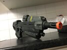
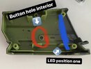
On my last post about the MA-40 on my ODST build, I said I was going to write up a thread on how to set up the lights in both the torch and ammo counter.

I’m going to break this down into 3 sections:
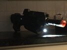
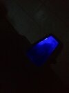
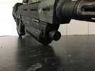
Introduction and what you need, the torch, and the ammo counter.

Without further ado, you’ll need:

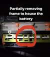
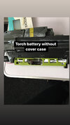
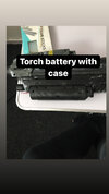
x2 23A Battery houses and batteries ( You can get those here: 12 volt power supply. 1x 23a 12v battery holder & battery. MN21 A23 etc 3949547972258 | eBay )

x2 Blue LED lights (You can find these here: DC12V 5mm LED Bulb Pre wired Light Emitting Diodes Small 20cm Wire for Hobbyists | eBay )

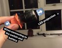
x1 Eagle eye LED (You can find these here at: 2/3/4/10X 12V Eagle Eye LED Daytime Running DRL Backup Light Motorcycle Car Lamp | eBay ) (You’ll get two in one pack, but you only need the one)

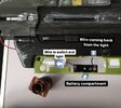
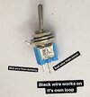
A Sub Miniature Toggle Switch (You’ll find these here at: On/Off Sub-Mini Toggle Switch Miniature SPST Hobby Model Railway On/Off Sub-Mini Toggle Switch Miniature SPST Hobby Model Railway: Amazon.co.uk: DIY & Tools )

X1 push switch (found here: 2PCS 12V Waterproof Push Button On-Off Switch With 4" Lead Wire Black | eBay ) (Like the Eagle Eyes, you’ll get two in a pack, but you only need one)

A Soldering Iron (If you’re like me and bought one specifically for this project, you can get one here: Silverline 643115 Soldering Iron,... https://www.amazon.co.uk/dp/B000O56TSI?ref=ppx_pop_mob_ap_share )

And of course, solder wire (Found here: GTSE 0.8mm Lead Free Solder Wire... https://www.amazon.co.uk/dp/B08GGC3MD9?ref=ppx_pop_mob_ap_share )
 

Attachments

  • 6FB5CEB9-4059-41E6-88AB-C14CC120A13D.jpeg
    6FB5CEB9-4059-41E6-88AB-C14CC120A13D.jpeg
    1.6 MB · Views: 542
  • CCE98D52-5E73-4EBB-8675-0AB55C6794DC.jpeg
    CCE98D52-5E73-4EBB-8675-0AB55C6794DC.jpeg
    2.2 MB · Views: 454
  • D6DEB8B6-A70D-4DB0-BEC2-BA12A2C65BBE.jpeg
    D6DEB8B6-A70D-4DB0-BEC2-BA12A2C65BBE.jpeg
    2.2 MB · Views: 361
The Torch:

So effectively, we’re going to be making a torch and installing into the blaster.

We’re using these pieces:
X1 Eagle Eye LED
X1 23A Battery and Power Supply
X1 Sub Miniature Switch
We’re also using a Dremel and some superglue for this stage.


The first thing I did was unscrewed the whole gun so I could gain access to the dummy torch. I removed it, hollowed it out and drilled two holes through the back of the torch. As I had the idea of running the wires through the hole and out to the switch. This ultimately didn’t work out, and I ended up removing the entire back piece of the torch. But I’ll get to that later.

I had planned where the batteries were going to go, which was going to be in the dead space at the bottom of the blaster. So I took my dremel and took out a chunk of the plastic to allow easy access to the battery.

Once I had that done, the circuit began to take form. Battery goes to the switch, switch connects to the light, the black wire from the battery and light connect to one another, thus completing the circuit.

What I was not expecting was how tricky it was going to be to wire up the switch from the inside of the blaster. Because it has that rounded outer edge, it meant I had to first secure that in place, and then wire it up inside the blaster. I connected two red wires to the switch, one from the battery, one from the torch with my soldering iron. This may take a try or two to get right, I know it did for me.

Once your circuit works remove the part of the torch that I have marked with a red ring. This will help the keep keep the wires from being crushed by the torch.

Screw the whole gun back together and you should now have a working torch.
 

Attachments

  • D21A8904-F17D-4665-AA7C-CA48397FC44E.jpeg
    D21A8904-F17D-4665-AA7C-CA48397FC44E.jpeg
    1.7 MB · Views: 318
  • 5A37823F-59EE-4135-863B-70E24737D96F.jpeg
    5A37823F-59EE-4135-863B-70E24737D96F.jpeg
    160.2 KB · Views: 297
  • 6092AAE3-61BF-4CD9-95B2-1467E3D4B3CF.jpeg
    6092AAE3-61BF-4CD9-95B2-1467E3D4B3CF.jpeg
    146.6 KB · Views: 302
  • 599EEF85-A35A-4E1F-9277-8148FFBC638A.jpeg
    599EEF85-A35A-4E1F-9277-8148FFBC638A.jpeg
    1.7 MB · Views: 278
  • 12939EF3-70B7-4602-ABF2-FEC95D074B93.jpeg
    12939EF3-70B7-4602-ABF2-FEC95D074B93.jpeg
    199.6 KB · Views: 265
  • F1E8E10A-2712-43EA-A7BD-074C39490122.jpeg
    F1E8E10A-2712-43EA-A7BD-074C39490122.jpeg
    123.5 KB · Views: 266
  • 6C035D7D-0AE4-4CEA-BAAD-1C87D6A9E3B6.jpeg
    6C035D7D-0AE4-4CEA-BAAD-1C87D6A9E3B6.jpeg
    1.4 MB · Views: 284
  • FF8E8991-BF76-4FEF-948C-FDEEF4777256.jpeg
    FF8E8991-BF76-4FEF-948C-FDEEF4777256.jpeg
    151.4 KB · Views: 266
  • A33D9F41-9B6D-4E0B-93E5-3F2132155CDD.jpeg
    A33D9F41-9B6D-4E0B-93E5-3F2132155CDD.jpeg
    164.3 KB · Views: 248
  • D2B40AFF-A23E-4067-A5D4-78F590A78679.jpeg
    D2B40AFF-A23E-4067-A5D4-78F590A78679.jpeg
    178.5 KB · Views: 262
  • E277C3AE-5AC4-493A-A480-34A7AB6FAA50.jpeg
    E277C3AE-5AC4-493A-A480-34A7AB6FAA50.jpeg
    172 KB · Views: 251
  • D65370FF-641B-4527-9BD5-C3A57AF2C98D.jpeg
    D65370FF-641B-4527-9BD5-C3A57AF2C98D.jpeg
    171.4 KB · Views: 233
  • 665795E0-0868-4A5B-81C3-EEBDA96E705F.jpeg
    665795E0-0868-4A5B-81C3-EEBDA96E705F.jpeg
    132.1 KB · Views: 258
  • 5C343DB9-0246-47CB-B4C9-32A801A5CEED.jpeg
    5C343DB9-0246-47CB-B4C9-32A801A5CEED.jpeg
    158.9 KB · Views: 296
The Ammo Counter:

The Ammo Counter has the same concept as the torch, with an extra LED.

x1 23A battery house and battery
X2 blue LEDs
X1 Button Switch
(We’re also using a dremel in this stage)

I started by only unscrewing the ammo counter piece, so that I could gain access to the interior to plan the electronics.

Once I had my plan, I drilled a hole out for the switch, but unfortunately the hole I drilled was nowhere near large enough for the switch, so I had to make the hole substantially larger

I secured both LEDs down behind the ammo counter screen inserts with a piece of electrical tape and left the battery compartment free floating.

Using the soldering iron, I soldered all of the red wires to one of the switch wires, and all of the black wires to the other switch wire. Once the circuit was working, I put the whole thing back together, however it’s worth noting that you may want to cut the wires back slightly for a better fit.
 

Attachments

  • EDD5F229-1D89-4131-9AED-4D66E0D27E9D.jpeg
    EDD5F229-1D89-4131-9AED-4D66E0D27E9D.jpeg
    99.9 KB · Views: 347
  • 76E4E745-E2F7-44BF-98C0-615061B0CCB4.jpeg
    76E4E745-E2F7-44BF-98C0-615061B0CCB4.jpeg
    136.5 KB · Views: 225
  • 4BC82FE8-54C5-4E02-B732-47015209B5CE.jpeg
    4BC82FE8-54C5-4E02-B732-47015209B5CE.jpeg
    79.4 KB · Views: 187
  • 09D1369F-DB5A-434B-B63C-C83DA69F4490.jpeg
    09D1369F-DB5A-434B-B63C-C83DA69F4490.jpeg
    105.2 KB · Views: 223
  • B69F290C-7B6E-4453-9DAC-500BEEC80887.jpeg
    B69F290C-7B6E-4453-9DAC-500BEEC80887.jpeg
    2.2 MB · Views: 211
  • 46A77EF2-3AB3-49F2-949B-C1E12E8527E0.jpeg
    46A77EF2-3AB3-49F2-949B-C1E12E8527E0.jpeg
    2 MB · Views: 222
Status
Not open for further replies.
Back
Top