- Member DIN
- S068
I can't wait to see the shots of this suit out in the wild and in action!

It's Update Time!
...
...7 weeks and 4 days lay-turrrr...
View attachment 302652View attachment 302653View attachment 302654View attachment 302655
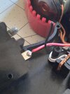
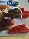
THE AUTO BLASTER IS DONE!
But it's far from over. As of right now, I've created enough space for me to get the parts to pop out as shown below.
View attachment 302656View attachment 302657View attachment 302658
However, the final part of the process of this prop, the mechanics of how to get it to work is currently in the making. I am currently in talks with a machinist, who studied at the University of Alabama, about making a system to make this idea into a reality.
So the plan is to make this pop out in the same fashion as it does on the first episode of Carranger. Red Racer pulls the fin back and in turn makes the "engine" move forward. The side panels pop out and the turbine spins in the process. Of course, I will have to insert the LED to make it light up, but will focus on that when the mechanic system is done.
To get a better idea on how it's suppose to turn out, simply go to the Shout Factory website and look for Engine Sentai Carranger Episode 1 after the 17 minute mark to see where I'm going with this.
That's all for now! Until next time!
Very funny that you demonstrated that idea in the picture. I was searching on how to make it open for days after the machinist told me on how to get it to work. He was the one to introduce me to movable cams and I looked on like on how to make it work on this prop. None that I've seen were possible because of the location and all the extra moving parts to get it going. That's when I came across this a week and a half ago.Apologies for using you render (it looks amazing by the way) but something simple like this may work to give the movement you want.
View attachment 302659
Grey blocks are just for extensions of the parts you need, blue rectangles are linkages that interconnect and the yellow circle is a pin the the center linkage rotates about. I'm not sure if your modelling software is good for simulating motion of parts but with the work we've seen you pull off I'm sure you can chunk through a problem like this.
Depending on how far it needs to go you could have a spring in tension holding the two halves shut and when you pull pack the central linkange presses forward into a wedge on another set in an arrangement similar to the one in the top left. That would make it reset back into place and when you pull back on the rear it extends the forward arm and presses the two side panels out simultaneously. Assembly of pieces might be a bit messy with so many parts in such a small space but everything is fairly simple.Very funny that you demonstrated that idea in the picture. I was searching on how to make it open for days after the machinist told me on how to get it to work. He was the one to introduce me to movable cams and I looked on like on how to make it work on this prop. None that I've seen were possible because of the location and all the extra moving parts to get it going. That's when I came across this a week and a half ago.
View attachment 302754
The mechanism encircled in red is the ONLY way I can make that possible. It's an ideal mechanism to open up the engine, but need to ensure that the panels open up at the same time. I will need to at least find the name of the mechanism so I can get a better idea to involve it as part of the design.
I was thinking about using Blender to create an animation simulation of the prop. So I will keep in mind as demonstration for advertisement when I go into mass production. But hey, if you have an idea on making it work, have it!
I went searching online after reading your post and there was this 1 word that reached out to me, linkage. So after 20 minutes of searching, I finally found the mechanism I was looking for. Reverse Linkage Motion. That is what the Z mechanism is called. Here's an example of it.Depending on how far it needs to go you could have a spring in tension holding the two halves shut and when you pull pack the central linkange presses forward into a wedge on another set in an arrangement similar to the one in the top left. That would make it reset back into place and when you pull back on the rear it extends the forward arm and presses the two side panels out simultaneously. Assembly of pieces might be a bit messy with so many parts in such a small space but everything is fairly simple.
"For some reason, the oddest things always happen around August to September that throws a monkey wrench into things..."
 www.405th.com
 www.therpf.com