You are using an out of date browser. It may not display this or other websites correctly.
You should upgrade or use an alternative browser.
You should upgrade or use an alternative browser.
Props ventrue's MA37 Assault Rifle (WIP)
- Thread starter ventrue
- Start date
- Status
- Not open for further replies.
nrettenmaier
Member
This is looking great, i really like the ammo counter you made.
That sucks your electromagnets didnt work out. I know u said you didnt want to make a solenoid yourself bit its really not that bad. I made one myself with 26 gauge (i think) wire and somehing like 500 turns and it works quite well. I just attached a fe neodynium magnets to the end of a dowel thats 1 inch by about 2.5 feet and it can push it about an inch and a half when kts just lying on the ground with no lubrication or anything. So far the only springs i can find (i havent looked TOO hard) are to stiff so i havent actually made a working model of it, but if you can minimize the friction it should actually work pretty well. Anyways, i just wanted to throw that out there in case the servos didnt work out.
That sucks your electromagnets didnt work out. I know u said you didnt want to make a solenoid yourself bit its really not that bad. I made one myself with 26 gauge (i think) wire and somehing like 500 turns and it works quite well. I just attached a fe neodynium magnets to the end of a dowel thats 1 inch by about 2.5 feet and it can push it about an inch and a half when kts just lying on the ground with no lubrication or anything. So far the only springs i can find (i havent looked TOO hard) are to stiff so i havent actually made a working model of it, but if you can minimize the friction it should actually work pretty well. Anyways, i just wanted to throw that out there in case the servos didnt work out.
Attention: Lots of text today. If you don't like text, press Ctrl+F4 now to reach the text-free version.
Progress:
Not much... again. That seems to get the standard opening line for posts in this thread, but what little time I had to work on this, I spent mostly researching stuff. Pictures of that are boring.
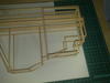
The picture below shows the basic magazine frame. As with the grip, the details around the bottom and on the sides will be add-on pieces. I know it looks very distorted, the reason for that is that it is distorted. I'll fix that later.
Also, I am trying to use an OLED display for the ammo counter, but the one I was trying to get to work has somehow.. ah... disintegrated. (Me trying to use a Dremel to remove some super glue might have had something to do with it, but personally, I am convinced that it was already broken when it arrived.)
I have ordered more, though, so this thread will definitely bring you some display fun, either in the form of pictures showing their total destruction or in the form of them actually working, which would be totally miraculous.
So, why do I want to use such a display in the first place? Several reasons:
Something else:
I have been getting mails asking for "plans" and "blueprints" and the likes, so I guess it's time I outline how I'm going to handle this:
Picture:

-----
It'll turn out amazingly awesome of course, because that's what I want it to be ;-)
Might take a while...
Then this was probably not what you had hoped for, sorry :-(
Thanks. I actually considered just making my own, but there are several reasons to go a different way. First, I would need a lot more power for solenoids, and cramming so many batteries into the model would be really difficult. Especially if they are supposed to be easily replaceable. It also would require relatively high voltages, I have to admit I'm not comfortable with that, because it requires actual safety precautions.
Progress:
Not much... again. That seems to get the standard opening line for posts in this thread, but what little time I had to work on this, I spent mostly researching stuff. Pictures of that are boring.
The picture below shows the basic magazine frame. As with the grip, the details around the bottom and on the sides will be add-on pieces. I know it looks very distorted, the reason for that is that it is distorted. I'll fix that later.
Also, I am trying to use an OLED display for the ammo counter, but the one I was trying to get to work has somehow.. ah... disintegrated. (Me trying to use a Dremel to remove some super glue might have had something to do with it, but personally, I am convinced that it was already broken when it arrived.)
I have ordered more, though, so this thread will definitely bring you some display fun, either in the form of pictures showing their total destruction or in the form of them actually working, which would be totally miraculous.
So, why do I want to use such a display in the first place? Several reasons:
- It can more accurately display the font used for the numbers
- You can display other stuff on it
- It's the easiest, if not only, way to get a decent looking direction indicator that can actually indicate more than one direction
Something else:
I have been getting mails asking for "plans" and "blueprints" and the likes, so I guess it's time I outline how I'm going to handle this:
- The printed, actual blueprints that are on my wall are Juliet76's (thanks again!), and the post that holds them says so very clearly. I will not send them anywhere, simply because they aren't mine.
- Obviously I'm also working off a reference picture I have imported into AutoCAD. It's total chaos, but you might consider it to be a "plan" as well. Since I am working on this as I go, it's not finished yet and I'm not happy to give it away in its current form. Should be kind of obvious, considering that I haven't made it available to download or even mentioned its existence so far.
- I may give my own files away in the future, but I haven't decided yet as to when, how or, most importantly, to whom. Let me just say that right now, your chances of acquiring these files are extremely slim, especially if you have registered only yesterday and the first thing you do here on the forums is sending me a one-line PM asking for them.
Picture:
-----
that looks amazingly awesome. Can't wait to see how this turns out
It'll turn out amazingly awesome of course, because that's what I want it to be ;-)
BAD-A$$!!!! Can't wait to see it complete!!!
Might take a while...
An interesting approach, but it's looking good :cool Can't wait to see the next batch of pics.
Then this was probably not what you had hoped for, sorry :-(
This is looking great, i really like the ammo counter you made.
That sucks your electromagnets didnt work out. I know u said you didnt want to make a solenoid yourself bit its really not that bad.
Thanks. I actually considered just making my own, but there are several reasons to go a different way. First, I would need a lot more power for solenoids, and cramming so many batteries into the model would be really difficult. Especially if they are supposed to be easily replaceable. It also would require relatively high voltages, I have to admit I'm not comfortable with that, because it requires actual safety precautions.
Attachments
I still feel bad about presenting you that single, lame picture in the other post... but I couldn't continue with the wood that day, the glue vapours are killing me (no, not literally I think, but in every other sense). I've decided that from now on, I'm going to wear my respirator while doing this stuff. No funny looks please!
Progress:
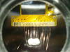
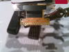
Some more fumeless electronic tinkering. Today's topic: Rotation!
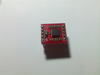
As I indicated in my last post, I want a direction indicator to indicate the direction. To do that, I obviously need to know the direction first, and that is where the red thing (or more precisely the little black thing on the red thing) in picture #1 comes in. It's a gyroscope and can detect rotation.
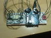
The short version is: It talks to the Arduino (picture #2), which does some cool math (nothing fancy, but "doing math" sounds good, right?) and can thereby more or less follow the direction in which the model is pointing. At the moment it's rather less than more, because there's still some tuning to be done here to make it more accurate. Especially repeatability is close to nonexistent, but I think it'll be good enough in the end to make it look realistic.
I've also put in a reset button to tell the Arduino where 0° or North is.
Granted, a magnetometer would probably do a better job at finding the direction, but I simply wanted to try out a gyro, that seems to have more potential for future projects. Maybe I'll switch sensors later, if it doesn't work.
I'm also getting to the point where I can't demonstrate the function with a picture, so I've decided to shoot two short videos, one of the ammo counter with servo and one of the gyro.
Note that I only have two 7-segment displays handy, so I can't display any angles above 99°. Beyond that, the thing displays nonsense.
Pictures:


Videos:
Progress:
Some more fumeless electronic tinkering. Today's topic: Rotation!
As I indicated in my last post, I want a direction indicator to indicate the direction. To do that, I obviously need to know the direction first, and that is where the red thing (or more precisely the little black thing on the red thing) in picture #1 comes in. It's a gyroscope and can detect rotation.
The short version is: It talks to the Arduino (picture #2), which does some cool math (nothing fancy, but "doing math" sounds good, right?) and can thereby more or less follow the direction in which the model is pointing. At the moment it's rather less than more, because there's still some tuning to be done here to make it more accurate. Especially repeatability is close to nonexistent, but I think it'll be good enough in the end to make it look realistic.
I've also put in a reset button to tell the Arduino where 0° or North is.
Granted, a magnetometer would probably do a better job at finding the direction, but I simply wanted to try out a gyro, that seems to have more potential for future projects. Maybe I'll switch sensors later, if it doesn't work.
I'm also getting to the point where I can't demonstrate the function with a picture, so I've decided to shoot two short videos, one of the ammo counter with servo and one of the gyro.
Note that I only have two 7-segment displays handy, so I can't display any angles above 99°. Beyond that, the thing displays nonsense.
Pictures:
Videos:
Attachments
Last edited by a moderator:
thatdecade
Well-Known Member
Wow ! That gyroscope really worked as promised. Any ideas for using the other axis?
Then this was probably not what you had hoped for, sorry :-(
Oh, don't get me wrong, I think it's shaping up great
Also, what you did with the gyro and electric ammo counter is incredible. Way beyond my ability with electronics.Wow ! That gyroscope really worked as promised. Any ideas for using the other axis?
How did you know there's a second axis?
But yes, there is one and actually it's another entry on the ever growing list of fails. The initial thought was: "Hey, people will probably aim up and down, lets get another axis, follow that angle as well and compensate for it". Then, module in hand, I realised that this isn't going to work (because it would need all three axes). I guess I'll have the opportunity here to buy even more cool stuff! :-D
what you did with the gyro and electric ammo counter is incredible. Way beyond my ability with electronics.
You can learn it! The stuff I used here is really noob-friendly. I already knew a few parts and basics from school and from playing around with science kits, but on that last breadboard-circuit, out of the seven different kinds of parts (yeah, it's really just seven, including microcontroller and wire), I have used four for the first time in this project. Everything else I've learned along the way (or haven't learned it and just try until it works ;-)).
hellphoenix36
Member
Ventrue, you're a beast. Keep up the awesome work!
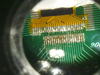
Progress:
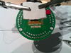
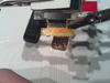
Some more soldering done on the display. Looks better than the first try and I'm pretty sure that I didn't short it out or melt it this time, and I definitely didn't fixate it prematurely with superglue. But I still haven't got it working. Must be the code and/or the circuit around it. If all else fails, I might have to take a well documented one with a breakout board and shamelessly reverse engineer that...
Anyways, despite not really making anything work here, I still got some pretty cool photos that you will certainly like.
You may ask yourself: Why am I not using a board with the correct pitch and just solder the thing on there directly, instead of fiddling around with enamel wire? Well, because there were no suitable boards in stock and this is the closest thing to a good solution that was available. Tough luck.
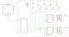
I also decided to get Eagle and try myself at making a circuit diagram. Image below. Looks pretty neat I think, but comes with a few strings attached: The entire gyro breakout board circuit is missing and the display controllers in the Eagle library don't have power pins for some reason. It would probably also be a lot better to give each segment its own resistor instead of using one for the whole digit and some pins could be saved by hooking all the buttons up to one of the analog pins. Either way, I think it's a lot clearer than a shot of a breadboard.
Basically this circuit is the combination of the two that I had previously showed you, they just don't fit on my breadboard at the same time. And of course, with only two digits, one would have to decide between displaying direction and ammo count.
Pictures:


-----
RAWR!
Some more soldering done on the display. Looks better than the first try and I'm pretty sure that I didn't short it out or melt it this time, and I definitely didn't fixate it prematurely with superglue. But I still haven't got it working. Must be the code and/or the circuit around it. If all else fails, I might have to take a well documented one with a breakout board and shamelessly reverse engineer that...
Anyways, despite not really making anything work here, I still got some pretty cool photos that you will certainly like.
You may ask yourself: Why am I not using a board with the correct pitch and just solder the thing on there directly, instead of fiddling around with enamel wire? Well, because there were no suitable boards in stock and this is the closest thing to a good solution that was available. Tough luck.
I also decided to get Eagle and try myself at making a circuit diagram. Image below. Looks pretty neat I think, but comes with a few strings attached: The entire gyro breakout board circuit is missing and the display controllers in the Eagle library don't have power pins for some reason. It would probably also be a lot better to give each segment its own resistor instead of using one for the whole digit and some pins could be saved by hooking all the buttons up to one of the analog pins. Either way, I think it's a lot clearer than a shot of a breadboard.
Basically this circuit is the combination of the two that I had previously showed you, they just don't fit on my breadboard at the same time. And of course, with only two digits, one would have to decide between displaying direction and ammo count.
Pictures:
-----
Ventrue, you're a beast. Keep up the awesome work!
RAWR!
Attachments
thatdecade
Well-Known Member
Highly recommend the sparkfun eagle part library and batchpcb.
Love the tracing wire, good luck.
Love the tracing wire, good luck.
hellphoenix36
Member
i wish i understood half of what u said here xD This looks awesome
Very nice work Ventrue
This is what i would like to evolve my simple ammo counter circuit into eventually so it opens up more input/output pins on the arduino.
How easy are the 7411 to use? (I might have to borrow some of your ideas Code especially as im not a very good programmer)
Cheers.
This is what i would like to evolve my simple ammo counter circuit into eventually so it opens up more input/output pins on the arduino.
How easy are the 7411 to use? (I might have to borrow some of your ideas
Code especially as im not a very good programmer)Cheers.
Highly recommend the sparkfun eagle part library and batchpcb.
Mh, I actually wanted to stick with perfboard for now. I don't think having custom PCBs made would really pay off here.
the ammo counter looks really sick man, keep it up
Thanks
i wish i understood half of what u said here xD This looks awesome
If you don't understand what I'm doing, feel free to ask questions. No guarantees though that I can answer them properly :-D
Very nice work Ventrue
This is what i would like to evolve my simple ammo counter circuit into eventually so it opens up more input/output pins on the arduino.
How easy are the 7411 to use? (I might have to borrow some of your ideas
The 4511s you mean? Well, these controllers want a BCD input. BCD means "binary coded decimal", basically a number of bits that stand for 1, 2, 4, 8 and so forth and have to be added up to whatever number you want to display. For example, 5 would be 4+1, so you'd have to input 1010. You can do that by just looking up a preset in an array or you can calculate it yourself in realtime, if you want some added coding fun ;-)
To be honest, using shift registers would probably have been easier, I just didn't have any (a problem that has been resolved since then... I went to my local supplier and said: "I want shift registers." He said: "How many?" and then I replied: "All you have."). You'd need one 8-bit register per digit here and three pins on the Arduino, regardless of how many digits you have. The 4511s, on the other hand, require four pins for the BCD and another one per segment for the latch.
hellphoenix36
Member
as much as i would like to ask questions, i would probably ask so much I would derail the thread, so maybe some other time in a PM
The 4511s you mean? Well, these controllers want a BCD input. BCD means "binary coded decimal", basically a number of bits that stand for 1, 2, 4, 8 and so forth and have to be added up to whatever number you want to display. For example, 5 would be 4+1, so you'd have to input 1010. You can do that by just looking up a preset in an array or you can calculate it yourself in realtime, if you want some added coding fun ;-)
To be honest, using shift registers would probably have been easier, I just didn't have any (a problem that has been resolved since then... I went to my local supplier and said: "I want shift registers." He said: "How many?" and then I replied: "All you have."). You'd need one 8-bit register per digit here and three pins on the Arduino, regardless of how many digits you have. The 4511s, on the other hand, require four pins for the BCD and another one per segment for the latch.
Oops yeah, the 4511s. Nice, they seem pretty straight forward.
I will eventually move to shift registers but i was after something simple (code wise) for the first version.
In regards to frame, do you find its robust enough in its current form?
Cant wait to see more!
Cheers,
Combust.
Ps. i will have to pick your brain when im up to the ammo counter in my build if thats ok?
as much as i would like to ask questions, i would probably ask so much I would derail the thread, so maybe some other time in a PM
Sure, feel free to PM me.
In regards to frame, do you find its robust enough in its current form?
[...]
Ps. i will have to pick your brain when im up to the ammo counter in my build if thats ok?
It's pretty solid, yes. Definitely strong enough to work with.
Sure. PM me as well.
- Member DIN
- S530
wow, quite the impressive build. I enjoyed reading through this. Keep up the good work, and then when you're done, make a real-life Spartan Laser! ...jk. But seriously, this is an awesome job, keep going don't let it die.
...jk. But seriously, this is an awesome job, keep going don't let it die.- Status
- Not open for further replies.
Similar threads
- Replies
- 0
- Views
- 1,026
- Locked
- Replies
- 0
- Views
- 906
- Replies
- 7
- Views
- 352
Similar threads
- Replies
- 0
- Views
- 906